

Explore CNC Cost, Tolerances & Supplier Selection
CNC machining tolerances describe how far a machined dimension may deviate from the nominal value on the drawing. General tolerances such as ISO 2768 give a starting point, while critical features need explicit limits and an agreed inspection method. Typical machined parts hold ±0.01–0.05 mm on well-controlled critical features, but the achievable value depends on material, geometry, tooling, temperature, and how the dimension is measured. The practical skill is not quoting a number, but specifying which dimensions matter and verifying them the same way twice.
The Tolerance Hierarchy: General, Critical, and GD&T
Tolerances work in layers. General tolerances — often taken from ISO 2768 — apply to dimensions with no explicit callout and cover normal machining variation. Critical tolerances are called out on the drawing for features that affect fit, function, or assembly. GD&T, such as positional tolerance, flatness, and concentricity, controls relationships between features rather than single dimensions.
The common mistake is treating a general tolerance table as a capability promise. A general ±0.1 mm on an uncontrolled dimension is not the same as a critical ±0.1 mm on a datum-referenced feature, because the second one is inspected, reported, and held by the process. Write the tolerance scheme on the drawing before quoting: a drawing that states which features are critical, which datum they reference, and how they are measured produces comparable quotes and defensible inspection results.
Typical Ranges by Material and Feature
The numbers below are typical ranges for well-controlled CNC work, not guarantees. Achievable values vary with the part, and every critical dimension should be confirmed during DFM review. Size also shifts the range: large parts accumulate thermal and fixturing variation across their length, so a 600 mm plate cannot hold the same tolerance per millimeter as a 30 mm block. Long parts need datums spread across the length and measurement at controlled temperature.
| Feature or material | Typical achievable tolerance |
|---|---|
| Aluminum, simple features | ±0.01–0.05 mm |
| Steel and stainless, simple features | ±0.01–0.05 mm |
| Small turned diameters | ±0.005–0.02 mm with grinding or finishing passes |
| Deep pockets and thin walls | ±0.05–0.15 mm, material dependent |
| Plastic parts | ±0.05–0.15 mm, temperature and moisture dependent |
| Positional tolerances with GD&T | Confirmed per feature and datum scheme |
Material matters more than most people expect. Aluminum cuts predictably, stainless work-hardens, and plastics move with temperature and moisture, so a tolerance that is routine in aluminum may be difficult in nylon or 316 stainless at the same geometry.
What Actually Moves the Number
Five factors decide whether a tight tolerance is practical: material stability, feature geometry, tooling rigidity, thermal behavior, and inspection method.
Long, thin features deflect under cutting forces, so a thin wall or a long slender shaft cannot hold the same tolerance as a short, stiff block. Deep pockets force longer tools, which flex more; tight corners force small tools, which also deflect.
Temperature changes the size of both the part and the machine. Machining heats the material, and a part measured warm may fail a tolerance it passes at room temperature. Agree on the measurement temperature — typically 20 °C — and let the part stabilize before final inspection.
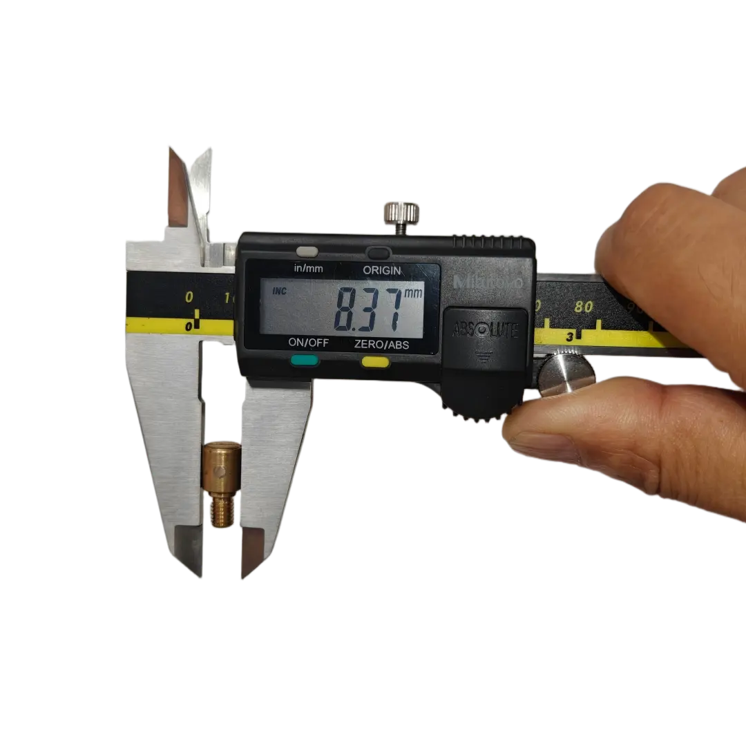
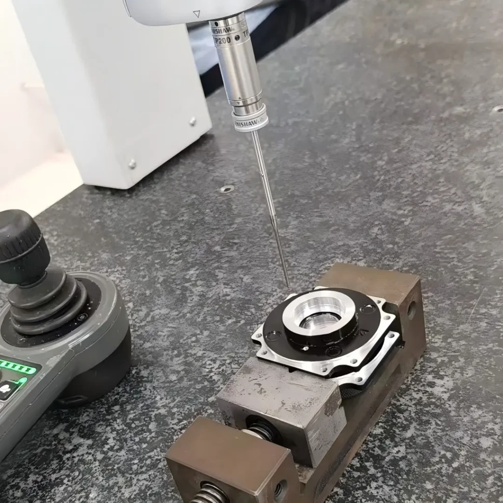
The inspection method is part of the tolerance. A CMM measures differently from calipers, and a soft plastic surface compresses under a contact probe. The drawing should specify the measurement method for critical features so supplier and buyer measure the same way.
Operator and process discipline is the fifth factor. Feeds, speeds, coolant, tool-wear monitoring, and measurement frequency separate a shop that occasionally hits a tolerance from one that holds it consistently across a run.
Tolerance and Cost: The Relationship
Tolerance and cost are linked, but not linearly. Relaxing a critical tolerance from ±0.01 to ±0.05 mm can cut cycle time and inspection cost significantly, while tightening from ±0.05 to ±0.01 mm may require finishing passes, better fixturing, and slower feeds. The practical rule is to tolerance what matters and relax the rest. A drawing with three critical callouts is cheaper to make and easier to inspect than one with fifteen tight callouts, and the critical list should come from the assembly, not from a habit of tightening everything.
How to Specify Tolerances on a Drawing
Start with a general tolerance block, then call out the two or three features that actually matter. Over-tolerancing everything raises cost without improving the part, because every tight callout adds inspection and rejection risk. Use GD&T where the relationship matters — positional tolerance controls where a hole sits relative to a datum; concentricity controls how two diameters line up. Mark critical dimensions with a symbol or note and state the inspection method. A drawing that says “critical: Ø10.00 ±0.02, CMM per datum A” tells the supplier exactly what to hold and how to prove it. Clarify whether tolerances apply before or after finishing: anodizing and plating add material, and a drawing that states the condition of measurement prevents disputes between the machined and finished part.
Inspection: CMM, Gauging, and Reporting
First-article inspection measures the critical features before production, and CMM reports provide the traceable numbers. For higher volumes, in-process gauging and statistical checks maintain the tolerance across the run. Ask what the inspection report includes — which features were measured, the instrument, the datum setup, and the results against the tolerance. A report without the datum setup is hard to defend if a part is disputed.
Confirm how nonconforming parts are handled. A quality supplier quarantines, investigates, and documents the disposition rather than silently reworking, and that behavior matters more than the tolerance number on the brochure. For repeat orders, ask how the supplier maintains the tolerance across the run: in-process gauging, tool-wear monitoring, and periodic CMM checks catch drift before parts leave the machine.
Common Misconceptions
“Tighter is always better.” Every extra tight callout adds cost and risk. Tolerance only the features that affect fit, function, or assembly.
“General tolerance tables are guarantees.” ISO 2768 and similar tables describe normal variation, not verified critical-feature capability. Confirm critical dimensions individually.
“The CAD model carries the tolerance.” Tolerances live on the drawing and in the quality plan, not in the model — state them explicitly.
“Measurement is a formality.” The same dimension can pass with one method and fail with another, so agree on the instrument, datum, and temperature before ordering.
6CProto Expert Views
The number on the drawing is only half of the tolerance; the inspection method is the other half. Mark the critical features, reference them to datums, and agree on how they are measured before quoting. During DFM review, suppliers should flag tolerances the geometry cannot realistically hold, because it is cheaper to adjust the callout or the design before the part is made than to dispute it after.
Conclusion
CNC machining tolerances are practical, not magical: hold a small set of critical features to tight limits, use general tolerances elsewhere, and verify with an agreed inspection method. The achievable range depends on material, geometry, tooling, temperature, and measurement, so confirm each critical dimension during DFM review. Write the tolerance scheme before quoting, keep the critical list short, and require inspection reports that show the instrument and datum setup — that is how quoted tolerances become delivered parts.
FAQs
What is a good general tolerance for CNC machining? ISO 2768 medium or fine classes are common starting points, but general tolerances are not verified capabilities. Call out and inspect the features that actually matter.
Can CNC machining hold ±0.01 mm? Often yes on well-controlled critical features, depending on material, geometry, and inspection method. Confirm the specific feature during DFM — thin walls, deep pockets, and soft materials change the answer.
What is the difference between ± tolerance and GD&T? A ± tolerance limits a single dimension; GD&T controls relationships such as position, flatness, and concentricity relative to datums. For assembly fit, GD&T is usually more meaningful.
How do I know a supplier can hold the tolerance? Ask for DFM feedback on each critical feature and require a first-article CMM report showing the datum setup and measured values. A supplier that names the inspection instrument for each critical feature usually knows what the tolerance actually requires.
Why do plastic parts have looser tolerances? Plastics move with temperature and moisture and deflect more under cutting forces, so achievable tolerances are wider than in aluminum or steel. Confirm the range for the specific grade and geometry.