

Explore Vacuum, Urethane & Metal Casting Guides
A hypothetical 1% linear shrinkage means roughly 1 mm across a 100 mm feature. That simple illustration explains why casting shrinkage belongs in tooling review before a drawing is released. It does not tell a toolmaker which percentage to apply to a particular alloy, resin, or silicone mold.
What casting shrinkage means for quote-ready drawings
Casting shrinkage should be specified as a validated relationship between tooling dimensions and conditioned part dimensions, not a universal percentage. Separate material contraction from warpage, tool movement, and measurement effects. Use grade-specific supplier data to establish an initial allowance, then confirm critical features on representative castings before approving production tooling.
Two dimensions belong in the discussion: the required finished feature and the feature that creates it. Keep the released part model at its intended finished size. Put compensation in a separately identified manufacturing model, with responsibility assigned to the toolmaker. Otherwise, a buyer may scale the CAD while the supplier independently adds another allowance.
Identify functional datums, mating interfaces, and the inspection state on the drawing. A housing measured immediately after demolding cannot be compared meaningfully with a conditioned first article unless the acceptance procedure permits that comparison. The 6CProto standards and tolerances page provides a discussion starting point; the purchase drawing must still define this casting’s actual requirements.
Metal casting vs resin casting shrink behavior
Metal and resin routes require different evidence before an allowance is selected. Metal casting involves feeding and solidification as well as subsequent cooling; a dimensional allowance alone cannot correct a cavity left by inadequate feeding. The American Foundry Society’s defect-analysis curriculum specifically treats solidification shrinkage as a casting-quality issue.
Resin casting adds cure chemistry, formulation, section thickness, and the specified cure schedule. A resin described as ABS-like is not an ABS injection-molding grade, so an ABS molding shrinkage number is not a defensible substitute. Obtain the exact casting resin’s technical bulletin and check how its reported shrinkage was measured.
The decision is therefore about the manufacturing route first, and compensation second. For a program comparing cast prototypes with later injection molding, maintain separate material and tooling assumptions. Matching nominal geometry does not make the shrinkage behavior transferable.
How shrink rates enter cavity and pattern design
Calculate an initial cavity size only after defining the denominator in the shrinkage rate. If linear shrinkage s is defined relative to the cavity dimension, finished length L equals cavity length C multiplied by (1 − s). The corresponding compensation is C = L / (1 − s).
For an illustrative calculation only, let L = 100.00 mm and assume s = 0.010. Then C = 100.00 / 0.990 = 101.0101 mm. These inputs are hypothetical, not a resin recommendation or a 6CProto capability claim. Multiplying by 1.01 gives 101.00 mm, a close approximation here but a different mathematical convention.
Do not substitute a volumetric percentage for s. Under an idealized isotropic model, a retained volume fraction must be converted to a retained linear fraction by taking its cube root. Real parts may contract unevenly or be restrained by cores. Check length, hole spacing, and flatness separately before deciding that a single scale factor is useful.
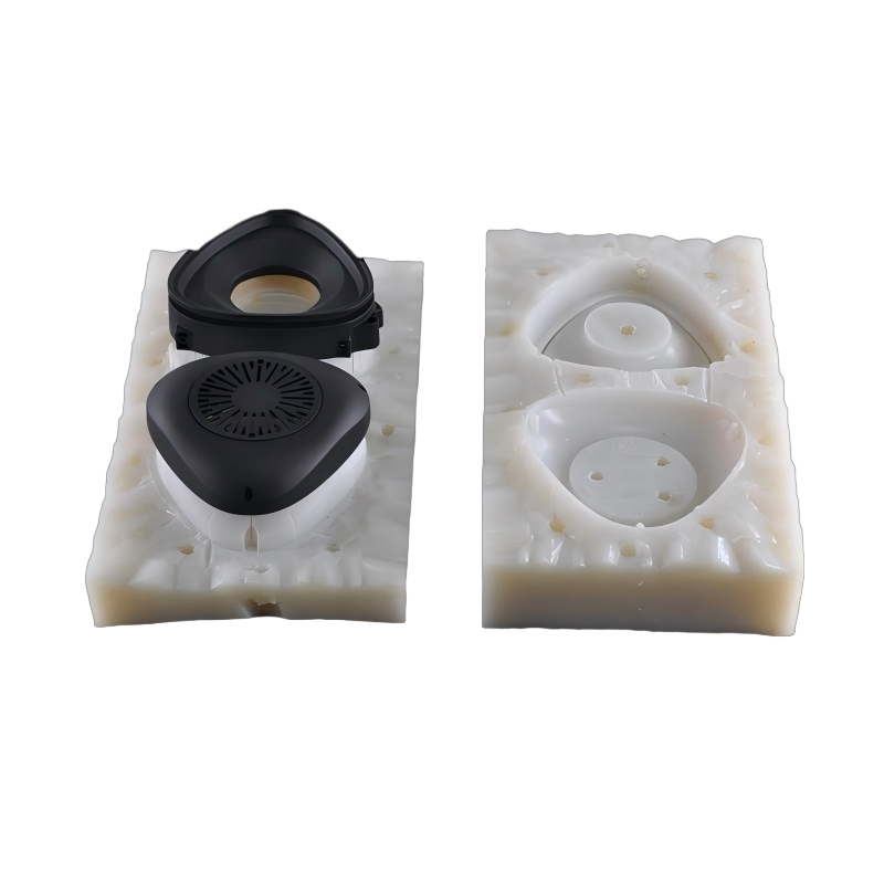
Where uniform walls and gates change local shrink
A thick boss attached to a thin wall can cool or cure differently from the surrounding shell. Enlarging the whole tool may bring the outside length closer to target while leaving the boss region distorted. Before changing scale, compare the dimensional error with the location of thickness transitions, gates, cores, and demolding loads.
For metal parts, review feeding and local solidification with the foundry. For thermoset resin parts, check whether the selected formulation suits the casting mass and thickness. Smooth-On’s Crystal Clear EU processing guidance links inappropriate resin selection and casting configuration with exotherm, shrinkage, and warping. Its recommendations apply to that product family, not every casting resin.
Ask for a marked-up section view rather than a blanket request to make walls uniform. Some bosses and sealing lands must remain thick for function. Possible responses include changing the local geometry, adjusting the manufacturing method, or leaving stock for a separately controlled finishing operation.
Table: typical shrink ranges by process family (verify with supplier data)
A useful casting shrink rate chart states its material and measurement conditions. There is no single defensible numeric range covering all alloys, resin formulations, mold systems, and geometries in this comparison. Use the following table to obtain comparable evidence before entering a value in a tooling specification.
Each row identifies the missing input, rather than suggesting an unverified industry average. A published material value is an initial estimate until it has been checked against the proposed part and process.
| Process family | Rate to obtain | Conditions to record | Validation feature |
|---|---|---|---|
| Metal casting | Alloy- and route-specific linear allowance | Mold system, restraint, heat treatment, finishing | Datum-based spans and machining stock |
| Rigid polyurethane casting | Exact formulation’s linear cure shrinkage | Section thickness, cure, post-cure, test age | Length, boss spacing, mating profile |
| Silicone tooling | Exact mold rubber’s dimensional change | Cure chemistry, storage, casting exposure | Cavity references or repeat cast features |
| Injection-molded comparison part | Grade- and direction-specific molding shrinkage | Processing window, flow orientation, conditioning | Flow and transverse dimensions |
Do not average the rows together. In particular, rubber-tool dimensional change and resin shrinkage belong to different stages of a replication chain.
How to specify compensation without guessing alloys
Specify the finished result and require the supplier to document the proposed compensation basis. A purchase specification should identify the exact alloy or resin grade, drawing revision, critical characteristics, and acceptance condition. If a grade remains undecided, ask for alternatives with separate assumptions rather than concealing the uncertainty inside one tolerance.
Agree the reference temperature for dimensional inspection. NIST’s Engineering Metrology Toolbox identifies 20 °C as the international reference temperature for dimensional measurements. A warm casting and a room-temperature reference can disagree because of temperature alone; this does not establish that the mold needs correction.
Define whether dimensions apply before or after machining, coating, and any specified conditioning. Keep a change record when a resin grade, cure schedule, or tooling model changes. For a critical interface, approve the inspection method alongside the drawing so that a later acceptance dispute does not become an argument about incompatible measurement setups.
Vacuum casting and silicone-tool shrink stacking
Vacuum casting shrinkage can accumulate through the master, silicone cavity, and cast resin. Measure the master before making the tool, then relate trial castings to that measured reference. Without that separation, an undersized master may be mistaken for excessive resin contraction and corrected at the wrong stage.
Silicone chemistry matters. Smooth-On’s comparison of tin-cure and platinum-cure silicones notes greater time-dependent shrinkage in tin-cure molds, with behavior dependent on the rubber, casting material, mold configuration, and other variables. That observation supports documenting the mold system; it does not supply a universal allowance.
Low initial shrinkage also does not mean unlimited dimensional stability in service. The manufacturer’s Smooth-Sil 950 instructions discuss mold use, release agents, and storage. For a urethane casting program, record tool identity and casting sequence so that changing results can be traced to a particular mold rather than pooled across the batch.
RFQ checklist for shrink assumptions
An RFQ should let the supplier distinguish a compensation estimate from an acceptance commitment. Attach the nominal CAD and controlled drawing together, then identify which file governs dimensions. Include mating-part information where assembly fit matters more than an isolated overall size.
The technical review should resolve the following items before a tool is released. Keep the answers with the quotation so that a purchasing revision does not silently change the engineering assumptions.
- Exact material grade and whether substitutions require approval.
- Owner and revision of the compensated tooling model.
- Source and definition of the proposed shrinkage value.
- Inspection datums, support arrangement, temperature, and conditioning state.
- Features requiring trial measurements before compensation is finalized.
- Finishing stock and the point at which dimensions become acceptance dimensions.
- Response when a local feature fails while overall scale remains acceptable.
Request a first-article comparison showing actual readings against the drawing. An approved visual sample alone cannot establish dimensional conformity. Where a feature is difficult to measure, settle the fixture or measurement method before production approval.
FAQ
These questions address approval decisions that arise after the initial compensation proposal. Keep the answers with the controlled project specification.
Can an existing master be used without rescaling it?
Yes, if its measured geometry and the planned replication chain leave enough dimensional margin. Check the master against the released drawing before assuming it is nominal. If only one interface is critical, a local tooling correction or finishing operation may be more appropriate than changing the entire master. Record the master revision so that a later replacement does not introduce an unnoticed dimensional change.
Should a supplier reuse the same allowance after a resin substitution?
Only after evaluating the replacement formulation and its processing requirements. Similar color, hardness, or ABS-like labeling does not establish equivalent cure shrinkage. Ask for the replacement technical bulletin, the proposed cure schedule, and a trial measurement of the affected functional features. Keep the original approval separate from the substitution decision; a successful casting in the previous resin does not validate the new one.
Can an assembly fit check replace a dimensional report?
It can supplement the report when the assembly test and mating references are controlled, but it may hide compensating errors. Two incorrect parts can fit each other while failing interchangeability with another batch. Define the assembly fixture, reference component revision, and pass criteria, then retain readings for the critical drawing features. Use the fit check to evaluate function without losing traceability to the specified geometry.
Next steps with DFM review
Release compensation when its basis is clear enough for another engineer to reproduce the decision. The strongest record connects a material bulletin, controlled tooling revision, trial measurement, and acceptance condition. Where the evidence shows local distortion, revise the relevant geometry or process instead of repeatedly changing global scale.
For 6CProto review, prepare the nominal CAD, dimensioned drawing, proposed material, and a short list of functional interfaces. Identify which assumptions are open so that the review can distinguish material selection, tooling correction, and inspection requirements. Pricing and delivery depend on the resulting project specification and require a quotation.
Upload your CAD and drawing to request a quote and DFM review. Ask for the proposed shrinkage basis to be included in the technical response before authorizing tooling.