

Updated
For engineers and buyers, the most useful starting point is a functional drawing: mating sizes, geometric relationships, material condition, surface requirements and acceptance evidence. This guide shows how those requirements affect process choice, workholding, finishing and a comparable RFQ.
Define what makes the turned part precise
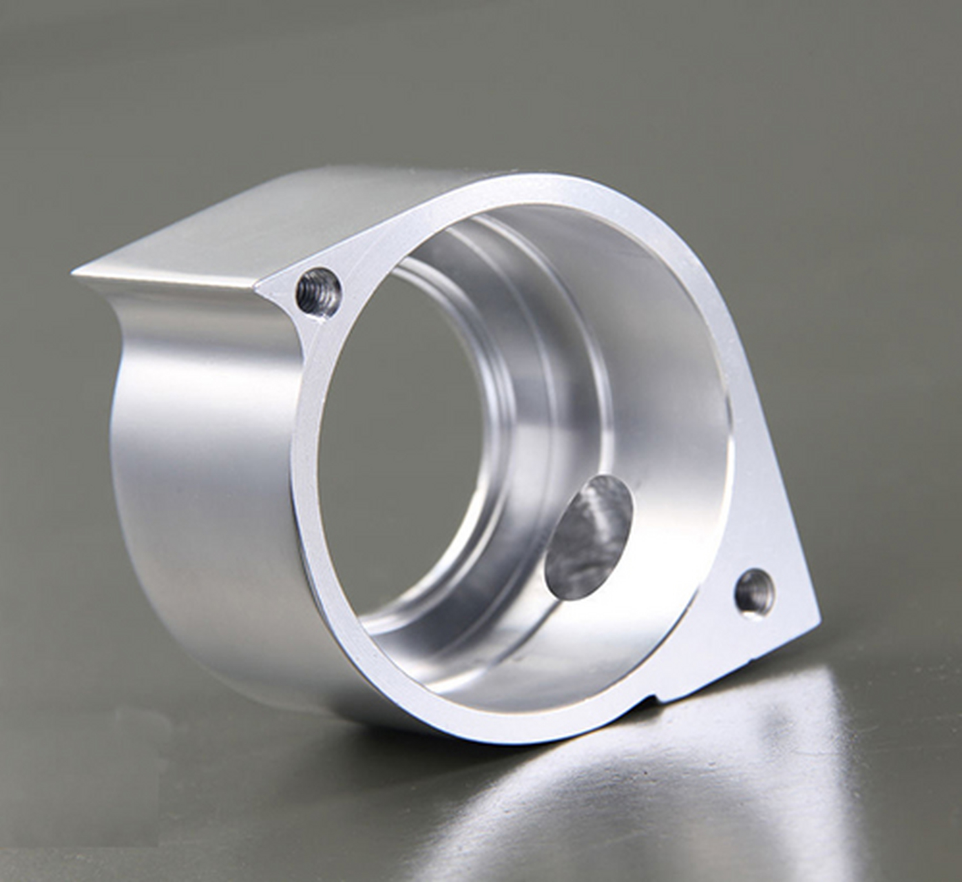
CNC turning removes material from a rotating workpiece to generate diameters, bores, shoulders, tapers, grooves and threads. Live tooling or a secondary operation can add flats and cross holes. The process is a strong candidate for shafts, bushings, sleeves and housings, but the presence of cylindrical geometry does not establish the best route for every feature.
Define precision through the assembly. A locating diameter may need a controlled clearance, a rotating journal may need a form requirement, and a shoulder may need orientation to a datum axis. These are different characteristics. A diameter tolerance alone does not guarantee roundness, straightness or the relationship between separated seats.
Start with CNC turning capabilities as a process overview, then identify the part-specific controls. A supplier’s general capability statement cannot replace a feasibility review of a long, thin, interrupted or thermally sensitive feature. Tie every demanding requirement to its function so the machining and inspection effort goes where it matters.
Separate size, form and datum relationships
Use distinct controls for distinct failure modes. A micrometer can establish local size within the chosen measurement method, but it does not fully characterize a complex geometric relationship. The ASME Y14.5 standard provides a framework for communicating dimensioning and geometric tolerancing requirements.
| Functional question | Drawing information to resolve it | Acceptance consideration |
|---|---|---|
| Will a shaft fit the mating bore? | Shaft and bore limits; clearance or interference intent | Measure both parts in the specified condition |
| Will the journal rotate as required? | Relevant form or runout control and datum definition | Agree how the axis is established and sampled |
| Will a flange locate squarely? | Shoulder orientation relative to the functional datum | Support the part without distorting it |
| Will a threaded connection assemble? | Thread system, size, pitch, class and engagement | Use the appropriate thread inspection method |
An ISO-based drawing should use its stated conventions consistently; ISO 1101 addresses geometrical tolerancing. Do not mix symbols or default interpretations casually. For a deeper diagnosis of axis-related problems, see the turning concentricity and measurement guide.
Set mating limits before tightening the whole drawing
Begin with the assembled fit rather than a favorite bilateral tolerance. Obtain the mating-part limits and calculate the worst-case clearance or interference. Include final treatment, operating temperature and any deformation that matters. A tolerance can look small on a drawing while consuming the full assembly margin.
Consider a hypothetical shaft specified at 19.980–19.990 mm and a mating bore at 20.000–20.010 mm. Minimum diametral clearance is 0.010 mm; maximum is 0.030 mm. This is a simple size example, not a recommended bearing fit. It says nothing about form, alignment, loading or differential thermal expansion.
Use this analysis to identify which dimensions need dedicated limits and which can follow the drawing’s general tolerance rule. Over-tightening cosmetic lengths or nonlocating exterior diameters adds machining and measurement work without necessarily improving the assembly. Conversely, a broad general tolerance may leave a functional journal inadequately defined. Review the complete stack whenever the mating component or finish changes.
Choose turning, turn-mill or a combined finishing route
A part with several coaxial diameters is naturally suited to turning, but secondary features can change the plan. Cross holes, flats and off-axis threads may be made with live tooling or on another machine. The best choice depends on access, datum transfer, quantity and the required relationship between the turned and milled features.
A single setup can reduce handling and preserve some relationships, but it does not eliminate tool reach, collision or stiffness limits. Ask which features will be completed together and which require re-clamping. If a flange hole pattern locates to a bore, the process should preserve that relationship through the secondary operation and inspection.
Grinding may be appropriate for a particular finished journal, while another surface remains turned. Hardness and surface-integrity requirements can also influence the sequence. Compare the proposed route feature by feature rather than assuming a machine with more axes automatically gives a better result. The RFQ should permit a technically sound combined route if the drawing does not mandate a particular manufacturing method.
Review long shafts, thin walls and difficult bores
Length, wall thickness and unsupported reach influence turning stability. A long shaft may need support that avoids bending or marking the final surface. A thin sleeve can become oval under chuck pressure and change shape when released. A deep bore may require a long boring bar that cannot maintain the same behavior as a short, accessible cut.
State whether acceptance applies in the free state or under a specified restrained condition. For flexible parts, inspection fixtures can change the result as much as machining fixtures. A round reading while the sleeve is clamped does not establish its free-state shape. Agree on support locations and forces when the part is particularly sensitive.
During DFM, review whether a thicker temporary section, a revised order of operations or a modest geometry change would improve stability. Avoid arbitrary length-to-diameter cutoffs; material, support, tool reach and feature requirements all matter. Request a specific plan for the difficult features instead of treating a published size envelope as proof that the entire part is straightforward.
Specify stock grade and final material condition
“Aluminum,” “stainless” and “steel” are incomplete purchasing descriptions. Grade, temper, heat-treatment condition and product form can affect machinability and final performance. Define the required specification and identify whether a material certificate, lot traceability or a hardness record is part of delivery.
If heat treatment occurs after rough turning, leave an agreed finishing allowance and maintain a usable datum strategy. If the part is supplied hardened, the route may require hard turning or grinding. Stress redistribution can also matter on slender or heavily pocketed components, so the process sequence should be discussed before a final capability claim is accepted.
For polymers, moisture conditioning and temperature can alter dimensions and behavior. Ask when measurements will be taken and how the supplied condition will be recorded. Do not apply a metal inspection assumption automatically to an engineering plastic. The material designation, manufacturing route and measurement condition should refer to the same released part, not three loosely related versions of the design.
Treat surface finish and coating as dimensional requirements
Specify texture only where it serves a function or an agreed appearance standard. A seal track, sliding fit and decorative exterior may require different preparation. “Smooth finish” is not an inspection criterion, and the same Ra value can coexist with different tool-mark patterns or local defects.
Use an explicit parameter, units and applicable texture standard. ISO 21920-1 addresses profile surface texture indications. Where scratches or burrs create a distinct risk, define their acceptance separately. For turning marks, discuss how the functional area will be sampled and whether the inspection instrument can reach it.
Additive coatings change fit. For a deposited layer with 0.005 mm buildup on each side of an external diameter, the diameter increases by 0.010 mm; an internally coated bore decreases by that amount. This geometric example does not apply unchanged to anodizing, which also converts substrate material. Coordinate the surface finishing specification with final dimensional limits, masking boundaries and the inspection stage.
Agree on measurement conditions and methods
Identify how each critical characteristic will be accepted before machining starts. Size may be measured with suitable contact instruments; form, contour and datum relationships may require different equipment and setup. ZEISS form and contour measurement systems illustrate the distinction between dedicated form measurement and a simple diameter reading. Equipment choice still needs to match the feature and uncertainty required.
For close limits, define the measurement temperature or temperature compensation approach. NIST’s work on dimensional measurements at nonstandard temperatures addresses uncertainty associated with thermal conditions. A warm part and a cold mating gauge can disagree for reasons unrelated to the programmed diameter.
Also distinguish a calibrated instrument from a complete measurement result. NIST’s metrological traceability guidance connects traceability to a documented calibration chain and measurement uncertainty. Ask for the agreed method, relevant setup and reported results, not only an equipment list. A capability claim should refer to the final feature and its acceptance conditions.
Prepare an RFQ that makes quotations comparable
Send a revision-controlled model and drawing, material specification, quantity, finish and critical-characteristic list. State whether the order is a one-off development build, a pilot lot or a repeat production requirement. Include the requested inspection report and any material or finishing records so suppliers quote the same deliverable.
Ask each quotation to identify exceptions, proposed datum or geometry changes, secondary operations and dimensions that need clarification. Separate tooling and setup costs from recurring unit costs where relevant. Compare the complete route and acceptance package, because one price may include final coating inspection while another stops at an as-machined part.
Lead time should cover material availability, setup, machining, outsourced treatment, inspection and shipping assumptions. A generic fast-turn claim cannot confirm a particular delivery date. If the schedule is critical, agree on the drawing-release date, approvals required and the effect of a revision after work begins. Clear inputs reduce quoting iterations and prevent procurement from choosing between superficially similar but technically different offers.
Use the first article to establish the repeat-order baseline
First-article results should connect the approved revision to measured critical features and the supplied material and finish. If the part passes only after a deviation or local repair, record the approved change and decide whether it belongs in the next drawing revision. Do not let an undocumented workaround become the repeat-production definition.
Before the next lot, resolve which process changes require notification and which records accompany delivery. A new material lot, alternate finish route or changed workholding may affect different characteristics. The appropriate review depends on the part risk; repeating every development test is not always necessary, but assuming all previous evidence transfers is equally unreliable.
Retain mating-part feedback as well as dimensional results. If assembly exposes a problem that the drawing did not control, revise the relevant requirement rather than merely asking for “more precision.” The repeat-order goal is a stable functional part with clear acceptance, not progressively tighter tolerances without an identified cause.
For a comparable quotation, send 6CProto your turning RFQ with the current model, drawing, material, final finish and critical-feature list. Include mating limits and the required inspection records for a part-specific review.
FAQ
Does a tight diameter tolerance guarantee concentric bearing seats?
No. Size and the relationship between seats are separate requirements. Define the functional datum and the relevant geometric control, then agree on an inspection method that evaluates that relationship.
Can a turned part include flats and cross holes?
Yes. They may be produced with live tooling or secondary machining. The choice depends on access, quantity and the relationship to turned features. State which relationships must be maintained across setups.
Should the supplier choose tolerances for my mating fit?
The design owner should define functional limits using the mating parts and service conditions. A supplier can provide DFM feedback and process feasibility, but a machining capability value does not determine the correct assembly fit.