

Updated
For rotating parts, do not use concentricity as a catch-all acceptance term. Specify whether the assembly needs surface runout, axis location or a legacy concentricity requirement. Those controls can produce different results on the same component, and they require different inspection strategies.
Choose the geometric control before tightening a number
For turning concentricity, define the relationship the assembly actually needs. Circular runout controls surface variation at individual circular sections relative to a datum axis. Total runout extends control across the specified surface. Position can locate a derived axis. None is interchangeable with a general instruction to keep a part concentric.
A radial indicator measurement contains effects from surface form and eccentricity as well as the measurement setup. It cannot, by itself, establish a legacy median-point concentricity result. Nor does a diameter measurement establish alignment to another feature. These distinctions matter when a seal surface, bearing register and internal bore all appear on one drawing.
The drawing must name its governing system and edition. ASME Y14.5 and ISO 1101 provide different specification frameworks; do not silently translate between them. For a legacy concentricity symbol, preserve the contractual interpretation or obtain an approved drawing revision before changing the acceptance method.
Runout, axis location and size answer different questions
Select the control by the failure you need to prevent. A centered but lobed surface and a round but offset surface can both generate indicator movement. Measuring only the bore diameter can miss either relationship to an external bearing seat.
The table separates the measurand from the instrument. A capable instrument still needs the correct datum construction, sampling strategy and evaluation settings.
| Requirement | What it evaluates | Suitable approach | What it does not prove |
|---|---|---|---|
| Circular runout | Variation around each specified section relative to the datum axis | Rotate on a valid datum simulator; inspect the required sections | Whole-surface total runout from a few isolated traces |
| Total runout | Combined variation over the specified surface relative to the datum axis | Rotate and traverse, or use an equivalent validated scan | Axis offset independently of surface form |
| Axis position or coaxial relationship | Derived feature location under the drawing rules | CMM or form system with the correct datum and extraction method | Surface texture or dynamic balance |
| Diameter and taper | Local size and axial size variation | Micrometer, bore gauge or appropriate air gauging | Alignment to a separate datum feature |
For example, ZEISS form-measurement systems offer separate evaluations for roundness, cylinder form and coaxiality. Treat those as distinct measurements rather than different names for one reading.
Build the axis from the functional datum feature
The datum axis should represent how the component locates in service. A shaft running in two bearing seats may need an axis established from those seats under the specified datum scheme. A sleeve located by its bore may need inspection on an appropriate bore simulator rather than on its cosmetic outside diameter.
The spindle axis is a manufacturing reference, not automatically the drawing datum. Likewise, center holes become an acceptance reference only if they correctly realize the specified datum requirement. Between-centers inspection does not remove every source of measurement error or prove that the working bore is aligned.
Review the datum feature length, form and accessible contact regions. A short register may make an axis sensitive to small local errors. On a CMM, changing the fitted cylinder or the alignment can change the reported relationship; ZEISS concentricity guidance illustrates the need to define the reference geometry. Establish a repeatable datum realization before using measurements to adjust the machining process.
Keep critical features connected through the operation sequence
Finish related diameters, bores and faces in the same setup when tool access and part stability permit. This avoids an additional locating operation, but it does not guarantee perfect alignment. Spindle error, tool deflection, thermal drift and clamp-induced distortion can still affect the finished surface.
When re-chucking is necessary, transfer location through a qualified machined feature. Soft jaws bored in place, a suitable collet or an expanding mandrel can support that strategy. Their value depends on contact length, cleanliness, clamping force and the form of the locating feature; the workholding label alone does not establish accuracy.
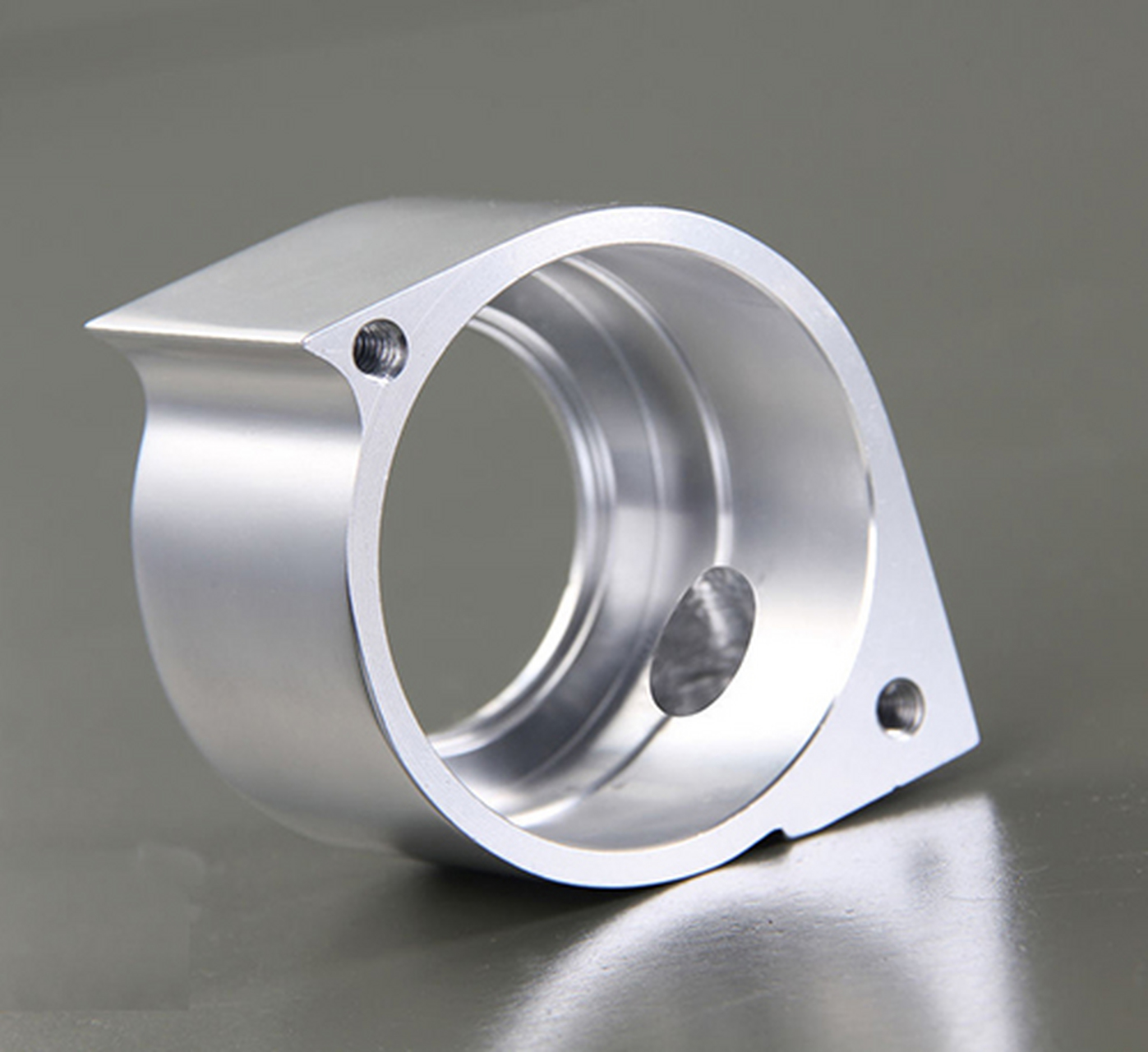
Plan where stock remains for the second operation and how the part seats axially. A chip behind the locating shoulder can tilt a component that otherwise centers well. Inspect the transfer feature and a reference surface before finishing the remaining critical features. The CNC turning process should be quoted around this sequence rather than around a generic machine accuracy claim.
Separate elastic deflection from permanent shape change
A long shaft can move during cutting, spring after unclamping or bend because residual stresses redistribute. These effects need different remedies. Tailstock support or a steady rest can reduce movement under cutting force, but excessive support force or poor alignment can also introduce error.
Compare the part before and after releasing the clamp. If a thin sleeve becomes out of round only after release, jaw pressure and the stiffness of the locating region deserve attention. If geometry changes after roughing or heat treatment, a revised stock-removal sequence or stabilization step may be more relevant than changing the chuck.
Control unsupported length and cutting load together. Use a supported, repeatable cutting strategy for slender sections, then verify the free or restrained condition required by the drawing. An inspection fixture should realize that condition. It does not have to duplicate the cutting setup if doing so would hide springback or reference the wrong axis.
Measure TIR without calling every reading total runout
TIR is the maximum indicator reading minus the minimum over the stated measurement. At a fixed axial section, rotating a cylindrical surface produces a circular-runout observation when the datum setup is valid. Checking three sections separately does not automatically constitute an adequate whole-surface total-runout evaluation.
For total runout, the evaluation must address the specified surface as a whole relative to the datum axis. Document how rotation, axial coverage and data processing establish that result. Avoid reporting only the largest of several local TIR values as though all surface variation had been captured.
Hypothetical arithmetic example: a radial indicator ranges from -0.006 mm to +0.010 mm at one section. TIR is 0.010 – (-0.006) = 0.016 mm. Only for an ideal round circle with pure parallel-axis offset does radial TIR equal twice the offset, giving 0.008 mm here. Lobing, tilt, taper and fixture error break that inference. The example is not a capability statement or a measurement of a 6CProto part.
Use error patterns to choose the next diagnostic check
Treat a runout pattern as a clue, not proof of one cause. Record amplitude and angular phase at several axial positions, then compare before and after re-chucking. A change introduced by a transfer operation directs attention toward locating surfaces, seating and clamp repeatability.
Increasing excursion along the shaft may indicate tilt or bending. A similar phase and excursion at several sections may suggest an offset, but surface form and the fixture can create overlapping patterns. Multiple lobes per revolution deserve a roundness assessment rather than an immediate jaw adjustment.
A useful diagnostic order is to clean and inspect the datum contacts, verify seating, repeat the mount, check the reference artifact or fixture, and then measure the part with a second appropriate method. Adjust one variable at a time. Repeated runs without controlled changes can show that a problem exists while providing little evidence of why it exists.
Make the inspection report explain borderline results
Record the datum realization, instrument, axial coverage, part condition and evaluation method alongside the result. Include actual values rather than only pass/fail where the data will guide a design change. For a borderline feature, agree on a conformance decision rule before production.
Calibration and traceability do not make measurement uncertainty disappear. NIST traceability guidance connects a measurement result to a reference through a documented calibration chain and uncertainty. Consider fixture repeatability, probing or indicator contact, sampling and the thermal condition in the measurement method.
Temperature should be stabilized where it matters, but uniform expansion does not automatically create runout in an otherwise ideal part. Thermal gradients, changing fixtures and compensation errors are the more relevant diagnostic questions. NIST work on nonstandard measurement temperatures explains why temperature and expansion-coefficient uncertainty affect dimensional results. This is a reason to record conditions, not to assert that every warm shaft is eccentric.
Specify only the relationships the assembly needs
Tighten the control on the feature that drives vibration, seal contact or bearing behavior, and justify the value from the assembly. Keep unrelated size and surface-texture requirements separate. A tighter diameter limit is not a substitute for a runout control, and low runout is not proof of acceptable dynamic balance.
Review the drawing against the standards and tolerances guidance and the planned machining route. Explain which locating surfaces are available after each operation and whether the acceptance condition is free, assembled or otherwise restrained.
The effective correction is the one supported by measurement: a cleaner locating shoulder, a different datum transfer, lower clamp distortion or a revised finishing sequence. Confirm that correction on released parts and repeat mounts. A good in-chuck reading is useful process evidence; the final result must still satisfy the specified functional datum requirement.
Send the drawing, datum scheme and required inspection condition through 6CProto’s quote flow. Identify the runout-critical surfaces so the DFM review can address workholding and operation order.
FAQ
Should a burr on the datum be removed before inspection?
Remove only burrs and contamination that the drawing or agreed preparation method permits removing. Do not improve the datum by polishing away functional material and then report the result as an untouched part. Record any preparation that could alter contact. If the burr itself is a manufacturing defect, preserve that finding even if cleaning makes the geometric measurement repeatable. The preparation procedure should be consistent across supplier and incoming inspection.
Can runout be inspected after assembling a bearing?
Yes, when the specified requirement is an assembly-level characteristic and the bearing arrangement realizes the intended operating reference. The result then includes effects from the bearing, mounting fit and assembly condition. It should not be reported as the isolated part result unless the procedure supports that interpretation. State preload, seating and the surface measured, and keep component acceptance separate where the drawing requires it.
What should change after replacing soft jaws or a mandrel?
Treat the replacement as a potential change to the locating and inspection process. Verify the contact condition, axial stop and repeat mounting behavior before relying on previous settings. Recheck representative critical features with the approved acceptance method, and preserve the fixture identity in the process record. The necessary extent depends on the control plan and risk; replacing a fixture does not automatically require repeating unrelated tests.