

What Causes Tool Deflection During Machining
Tool deflection is the unwanted bending of a cutting tool under machining forces. It can cause dimensional errors, taper, poor surface finish, chatter, broken tools, and inconsistent repeatability. Deflection occurs when cutting forces exceed the stiffness of the cutter, holder, machine setup, or workpiece. Long, narrow tools are particularly prone to bending because even modest side loads can move the cutting edge away from its intended path. The result is often an oversized pocket, an undersized external feature, a tapered wall, or an uneven finish.
The cutter behaves like a cantilever beam: stiffness decreases sharply as unsupported length increases. A small increase in stick-out can therefore create a disproportionately large increase in deflection. Tool diameter matters as well; a larger core is generally far more resistant to bending than a smaller one. Common warning signs include dimensional variation between roughing and finishing operations, tapered walls or bores, chatter marks and inconsistent surface texture, tool breakage near deep pockets or thin walls, parts that measure differently after unclamping, and repeated need for manual offset adjustments.
How Tool Geometry Affects Rigidity
Tool geometry strongly affects deflection because diameter, flute length, reach, core size, and material determine how much force a cutter can resist. The most rigid practical option is usually the tool with the shortest usable reach, the largest allowable diameter, and the smallest necessary length of cut. A common mistake is selecting a long-flute tool when only long reach is required: a long-reach cutter may have an extended non-cutting shank that clears surrounding geometry while retaining a shorter cutting length and a stronger core, which is preferable when machining deep cavities with limited access.
Tool material also affects stiffness. Solid carbide is generally stiffer than high-speed steel, although it is more brittle and can fail suddenly if cutting loads become unstable. Coated tools may improve wear resistance or heat management, but coating alone does not solve a rigidity problem. For prototype parts, engineers should avoid specifying internal corner radii that require extremely small cutters unless the function truly demands them. Increasing a corner radius may permit a larger end mill, reduce machining time, and improve dimensional consistency.
Which Cutting Parameters Reduce Deflection Risk
Cutting parameters reduce deflection when they keep forces stable, avoid excessive radial loading, and prevent rubbing. The best settings depend on material, tool geometry, machine rigidity, coolant strategy, and feature shape, so they should be developed as a controlled process rather than copied from a generic chart. Radial engagement is often the critical variable: a full-width slotting cut creates high side loads, while a lighter radial step-over reduces bending forces. High-efficiency milling strategies often use a smaller radial engagement with a deeper axial cut, maintaining more consistent chip thickness and reducing sudden load spikes.
Feed rate must be balanced carefully. Reducing feed too far can cause rubbing instead of cutting, which generates heat, work-hardens some materials, and can worsen finish; increasing feed excessively can overload the tool and fixture. The goal is stable chip formation, not simply the lowest possible cutting force. Spindle speed affects cutting behavior, but raising speed does not automatically solve deflection: at certain conditions, speed changes can excite vibration or chatter. A practical approach is to start from validated tooling data, then adjust one variable at a time while observing spindle load, sound, chip formation, surface finish, and measured dimensions.
How Toolpaths Control Cutting Forces
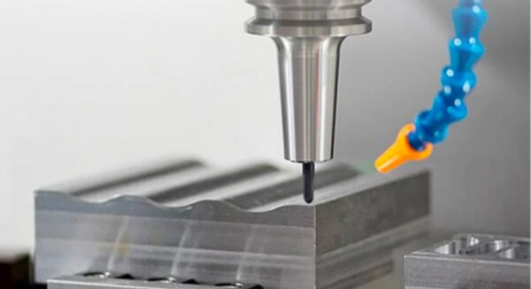
Toolpaths should keep cutting engagement smooth and predictable, because sudden direction changes, full-width engagement, and sharp internal corners create force spikes that bend the tool. A stable toolpath usually produces better finish and repeatability than an aggressive path that appears faster in simulation. Climb milling is commonly preferred for many CNC milling applications because the cutter enters material at maximum chip thickness and exits with a thinner chip, reducing rubbing and improving surface quality when the machine and workholding are sufficiently rigid; the appropriate strategy still depends on the machine condition, material, fixture, and geometry.
Useful programming practices include arc or tangent entries instead of abrupt plunges into finished surfaces; avoiding burying the tool in sharp internal corners; maintaining a consistent engagement angle where CAM software permits it; roughing material in stages before using a finishing tool; leaving controlled stock for finishing rather than attempting final size during heavy roughing; and considering a spring pass when measurement shows elastic recovery after the first finish pass. A spring pass repeats the same finishing path with little or no additional programmed stock removal, removing material left behind when a deflected cutter springs back. It should not be treated as a substitute for poor rigidity, but it can improve consistency on sensitive walls, thin sections, and close-tolerance features.
Why Workholding Matters as Much as Tooling
A rigid cutter cannot produce an accurate part if the workpiece moves, vibrates, or relieves stress after machining. Fixture deflection and workpiece distortion can resemble tool deflection, making the root cause difficult to identify without a structured setup review. Clamping force should secure the part without crushing thin sections or introducing distortion: over-clamping a plastic component, thin sheet-metal feature, or slender aluminum wall may create a part that measures correctly while held but moves out of tolerance after release. Soft jaws, sacrificial supports, custom fixtures, vacuum fixtures, and staged machining help distribute forces more evenly.
For complex parts, machining sequence matters. Removing substantial material from one side before supporting the opposite side can release internal stresses or reduce section stiffness. A better sequence may include roughing, intermediate stress relief where appropriate, re-fixturing, and light finishing cuts. When a drawing contains thin walls, deep cavities, narrow ribs, or difficult clamping locations, a DFM analysis is useful: it should focus on the part’s functional requirements and manufacturability risks, not solely on whether a feature can technically be cut.
Design Changes That Make Parts More Stable to Machine
Design changes can reduce tool deflection by allowing larger cutters, shorter reaches, better workholding access, and more balanced material removal. Small revisions to corner radii, wall thickness, cavity depth, and tolerances can substantially improve machining stability without changing the intended function. Internal corners are a frequent constraint: since round cutters leave radiused internal corners, an unnecessarily small radius requires a small end mill with low stiffness; if assembly conditions allow, increasing the radius improves access and reduces risk. Deep, narrow pockets that are many times deeper than their width require long-reach cutters, increasing the risk of wall taper and chatter; designers can sometimes reduce the depth, widen the opening, divide the feature, or redesign it as a separate component. Thin walls can deflect under tool force and rebound after cutting, leaving variable thickness; where function permits, thicker walls, temporary support tabs, or a different machining sequence may be more effective than tighter programming compensation.
When Should You Change the Manufacturing Process
A process change should be considered when machining deflection remains difficult to control despite reasonable tooling, fixturing, and toolpath improvements. CNC machining is versatile, but it is not automatically the best route for every thin, deep, flexible, highly repetitive, or near-net-shape component. A low-volume functional prototype may justify CNC machining for material flexibility and fast design changes; a higher-volume part with repeated thin-wall geometry may be better suited to injection molding, die casting, stamping, or another process that creates the shape nearer to final form. Early comparison of routes avoids validating a design with a prototype process that does not reflect the eventual manufacturing constraints.
Validate That Deflection Is Controlled
Teams can validate deflection control by measuring critical features, checking for repeatability across parts, comparing in-process and final measurements, and reviewing surface evidence. A part that meets nominal dimensions once is not sufficient proof that the process is stable. Start with the features most likely to show error: deep-wall thickness, pocket width, bore position, flatness, parallelism, and thin sections. Measure at multiple heights or locations to detect taper, and compare results before and after unclamping to identify distortion caused by fixture loading or stress release. CMM inspection provides detailed dimensional evidence for complex geometries when the inspection plan is aligned with the drawing’s functional datums; for qualifying projects, 6CProto states it uses CMM inspection. Inspection alone does not correct the process: when results vary, connect measurement findings to tool reach, tool wear, runout, workholding, material batch, and toolpath conditions.
FAQ
What is the simplest way to reduce tool deflection?
Use the shortest possible tool stick-out and the largest cutter diameter that the geometry allows. This usually provides the most immediate improvement in rigidity, although workholding and toolpath loading must also be stable.
Can a slower feed rate eliminate tool deflection?
Not necessarily. Lowering feed can reduce cutting force, but reducing it too much may cause rubbing, heat buildup, and poor chip formation. Feed should be matched to the tool, material, radial engagement, and machine stability.
Is a spring pass always necessary for finishing?
No. A spring pass is useful when the cutter or workpiece elastically recovers after the first finish pass, but it adds cycle time and does not address the underlying cause of excessive deflection. Use it based on measured results.
See CNC milling services, the DFM checklist, and the CMM inspection framework for validation planning. ASTM standards offer an external reference on materials and testing relevant to tooling and machining practice.