

A 3D printed enclosure that survives a drizzle test fails after a day under a hose — water finds the layer lines, the screw holes, and the seam where the lid meets the body. Printed enclosures leak at three places: through micro-porosity and layer paths, through unsealed fasteners, and at the lid seam. Each leak path has a design fix, and none of them is “add more wall thickness.” Watertightness in a printed part is a system of wall strategy, sealing features, and post-processing, and the system has to be designed before the first print, not discovered at the first leak test.
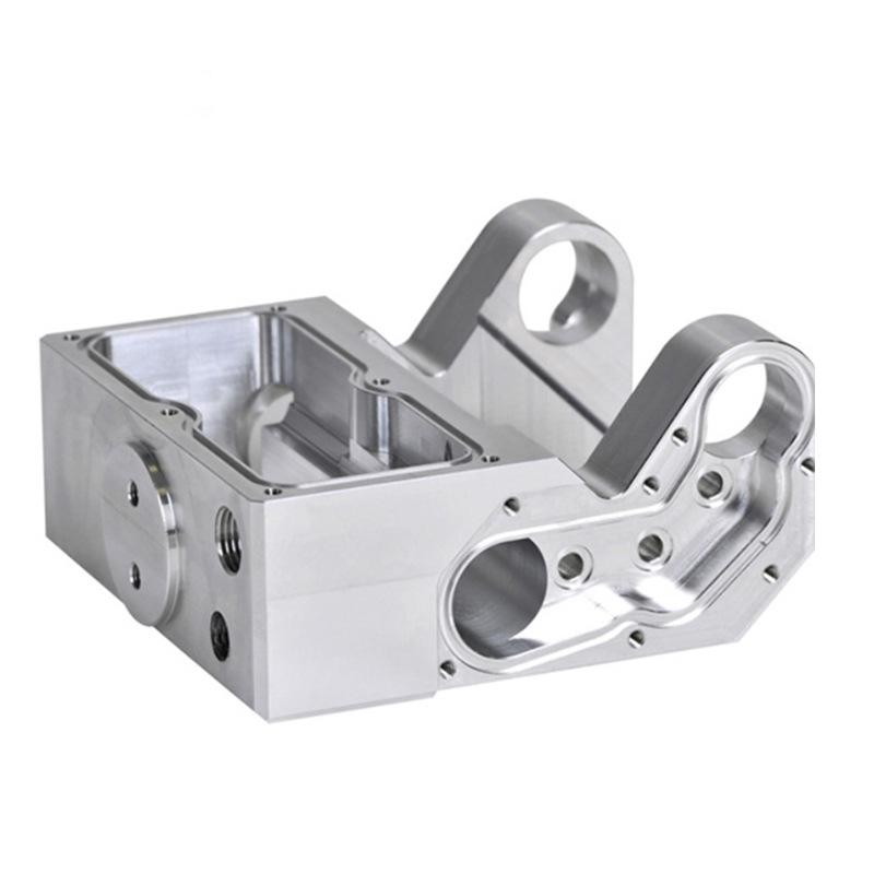
Why printed enclosures leak: layer paths, micro-porosity, and wall strategy
Printed parts are built from layers, and the layer interfaces are the first leak path: water can travel along the bonds between layers, especially in FDM parts where the layer adhesion is mechanical rather than fused. Powder-bed and resin parts can carry micro-porosity that connects internal voids to the surface, and thin walls in any process can leave pinholes. The wall strategy is the first defense: a solid wall of adequate thickness with complete layer adhesion is more watertight than a thin wall or a wall with sparse infill that can hold water. The wall must also be continuous — every screw boss, rib, or cutout that interrupts the wall creates a potential path.
Wall thickness alone is not the answer. A thick wall printed with poor layer adhesion still leaks along the layer paths, and a wall that is too thin flexes and opens the layer bonds under pressure. The design goal is a solid, continuous wall with the process set to maximize layer fusion, verified by testing rather than assumed from the CAD.
Wall thickness and infill choices for a watertight body
The watertight body needs solid walls at the sealing areas, with infill only where it does not create a path. A common approach is to print a solid shell of several perimeters with a dense or solid top and bottom, so the outer skin is continuous; infill inside the wall can trap water if it connects to a leak path, so the region around fasteners and the lid seam should be solid. The wall thickness should be sized for the process and the pressure: thicker walls resist flexing, but the layer fusion and the material choice decide whether the thickness actually seals. The process settings — extrusion width, layer height, and wall overlap in FDM; exposure and curing in resin — determine the continuity of the shell more than the CAD wall number does.
For resin and powder-bed parts, the wall strategy includes the internal structure: hollow parts need drainage or a sealed internal volume, and unsintered or uncured material inside a wall can weaken it. The design should state which surfaces are sealing surfaces and keep the wall continuous there.
Sealing ribs, gasket seats, and fastener compression
The lid seam is sealed by compression, not by the flatness of the printed faces. A printed gasket seat is rarely flat enough to seal against a flat lid without a gasket, so the design should include a gasket: an O-ring in a groove, a flat gasket between the lid and a sealing rib, or a molded seal that the lid compresses. The sealing rib concentrates the compression along a narrow, continuous line, which is more effective than a broad flat face on a printed part. The fastener pattern must compress the seal evenly around the perimeter, and the screw bosses need enough material and stiffness to hold the compression without cracking.
The gasket groove and the rib geometry should be sized from the gasket data: the groove width and depth control the squeeze, and the rib height and width control the pressure. A printed groove with rough walls can damage a soft gasket, so the groove surfaces may need post-processing or a design that accommodates the printed surface.
Post-processing seals: vapor smoothing, coatings, and dip sealing
Post-processing closes the layer paths that the print leaves open. Vapor smoothing melts and reflows the surface layer of nylon parts, closing micro-paths and improving the seal at the surface. Coatings — epoxy, urethane, or specialty sealants — can be brushed, sprayed, or dipped to fill porosity on the surface, and dip sealing is a practical route for complex enclosures. The post-process must be matched to the material and the application: a coating that is not rated for the environment can fail, and a smoothing step that changes the gasket groove dimensions can break the seal it was meant to create. The post-process should be part of the design specification, not an experiment at the first leak test.
Post-processing also affects the fasteners and the gasket: a dipped enclosure that coats the threads or the gasket seat changes the assembly. Mask the features that must stay clean, and verify the post-processed dimensions on the sealing surfaces.
Testing watertightness before committing to production molding
The printed enclosure is often a prototype for a molded production part, and the watertightness test should be designed for the transition. Test the printed enclosure at the pressure and duration the product will see, with the production gasket and fasteners, and record where the first leak appears: a leak at the seam points to the gasket or the fastener pattern; a leak through the wall points to the material or the post-process; a leak at a boss points to the fastener seal. The test result tells the design team what to change in the printed prototype and what to carry into the molded design, because molding changes the wall and the sealing behavior but not the gasket and fastener logic.
The enclosure design guide on this site covers the manufacturing route; this page is the watertight-design checklist for the printed stage. When the test passes with margin, the molded design can be developed with the sealing features that the prototype validated.
Testing and improving the first watertight build
A leak-test iteration shows how the system comes together. A printed enclosure prototype with a gasket and sealed fasteners is tested at the target pressure. The first leak appears at a screw boss where the screw passes through the wall: the fastener is sealed on the outside, but water follows the screw thread into the boss and leaks at the interior. The fix is a boss seal — an O-ring under the screw head, a sealed insert, or a design that keeps the fastener out of the water path. The second leak appears through the wall near a thin section where the layer adhesion is incomplete; the fix is a thicker solid wall and a process change that improves fusion at that location. The third test passes, and the design is frozen with the wall, the boss seals, and the gasket documented. Each leak pointed to a different system element, and the test sequence found them in order. Without the test, the enclosure would ship with the boss leak hidden until the field, where the failure mode is harder to diagnose.
The test also produces the data for the production transition. When the printed enclosure is a prototype for a molded part, the leak test results identify the sealing features that the mold must reproduce: the gasket groove, the boss seals, and the wall strategy. The molded part will not leak through layers the way the printed one did, but it will leak at the same seams and fasteners if the sealing design is not carried over. The transition plan should re-verify the molded part at the same pressure with the same gasket, because the material and the process change the behavior. The watertight design is a system of wall, gasket, and fastener decisions, and the test is what proves the system — at the prototype stage and again at production.
Ingress targets and printed reality need to be aligned at the start. A printed enclosure can be made watertight for many applications, but the ingress rating it can honestly claim depends on the material, the wall strategy, the post-process, and the sealing system — and the rating should be verified, not assumed from the CAD. If the product requires a high ingress rating, the printed prototype is the development vehicle, and the production route is likely molding with the sealing features the prototype validated. If the product is low-volume and the printed enclosure is the production part, the rating is earned by the post-process and the seal, and the test should cover the production configuration. The design should state the target, the test method, and the production route, so the watertight work is aimed at the right finish line. A printed enclosure that is developed against the real target and verified with the real test is a design that moves into production with its sealing system proven.
If you are developing a watertight printed enclosure and want the wall, gasket, and post-process plan reviewed before the first leak test, the 6CProto 3D printing team can work from your ingress requirement to the print and the seal design.