

What Interference Checking Identifies
Interference checking is the process of identifying unwanted physical conflicts between parts, tools, fixtures, machine components, or moving assemblies before manufacturing or operation. It combines CAD review, tolerance analysis, motion simulation, and process verification to reduce collisions, redesigns, scrap, tooling damage, and assembly failures. Effective checking begins early and continues through prototyping, production planning, and quality validation.
Interference checking identifies unwanted overlaps, collisions, insufficient clearance, restricted movement, and manufacturing access problems. It can be applied to assembled components, CNC toolpaths, injection molds, sheet metal parts, fixtures, fasteners, cables, and service access zones. Interference may occur when two bodies occupy the same space, a rotating component contacts a stationary housing, or a fastener cannot be installed because surrounding geometry blocks tool access. A clearance problem may not be a literal overlap: a small gap can still be inadequate after tolerance variation, thermal expansion, coating, vibration, or assembly misalignment is considered.
A valid check must also distinguish intentional fits from unacceptable interference. Press fits, seals, bearings, clips, and interference-fit joints may depend on controlled contact. The objective is not to eliminate every contact, but to verify that each contact is intentional, specified, and achievable under realistic conditions.
Interference Categories in Manufacturing
- Static interference. Overlap between components in a fixed position.
- Dynamic interference. Collision during rotation, sliding, folding, or articulation.
- Tool and fixture interference. Cutting tool or holder conflicts during machining.
- Assembly access interference. Fasteners, tools, or operators blocked during installation.
- Service interference. Removal, inspection, or replacement prevented after assembly.
- Process interference. Draft, bend relief, support structures, or mold mechanisms that trap the part.
Manufacturing interference checking expands the scope beyond the finished product. A CNC tool may reach the target surface but collide with a holder, vise, fixture, or adjacent feature. In injection molding, a mold insert may conflict with a slide, ejector, lifter, or parting surface. In sheet metal fabrication, a bend may be geometrically possible but impossible because the tooling cannot reach the flange.
How to Perform a CAD Interference Check
Engineers should begin with clean, correctly positioned CAD data, then check static clashes, motion ranges, installation access, and tolerance-sensitive clearances. The review should use the actual component versions, fasteners, fixtures, tools, and operating positions rather than simplified placeholder geometry. Findings should be recorded with an owner, a decision, and a revision reference.
A practical workflow is:
- Confirm the assembly structure, coordinate systems, units, and revision status.
- Suppress irrelevant details while retaining features that affect clearance or access.
- Run a solid-body interference calculation for fixed assembly positions.
- Inspect critical sections with transparent views, section cuts, and measurements.
- Simulate the full range of motion for hinges, slides, shafts, doors, and linkages.
- Check installation and removal paths, not only the final assembled condition.
- Review tolerance stack-ups at critical interfaces.
- Recheck the revised model and preserve the result in the design record.
Software-based detection is useful, but it does not replace engineering judgment. A CAD model may omit cable bend radius, gasket compression, paint thickness, burrs, or realistic tool envelopes, and a moving assembly may pass a coarse simulation while colliding at one angular position. Classify findings by consequence: a collision that prevents assembly differs from a cosmetic contact, and one that blocks a safety mechanism or damages a sealing surface deserves the highest priority. Avoid simply changing clearance values until the warning disappears; the design intent must remain clear.
Which Manufacturing Processes Need the Most Checking
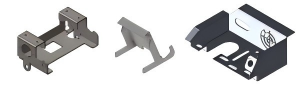
Processes with complex geometry, restricted access, moving tooling, or many tolerance-sensitive interfaces generally require the most intensive interference checking. CNC machining and injection molding often need the deepest review, with sheet metal fabrication and final assembly close behind.
- CNC machining. Toolholder versus part, spindle versus workholding, machine limits. Verified with toolpath simulation, reach analysis, fixture review, and setup verification.
- Injection molding. Parting line, slides, lifters, ejectors, draft, and mold-opening conflicts. Verified with mold-motion simulation, draft analysis, and shutoff review.
- 3D printing. Trapped powder or resin, support contact, build-volume limits, and fit variation. Verified with orientation review, clearance checks, and support and escape-path analysis.
- Sheet metal fabrication. Bend-tool access, flange collisions, bend sequence, and relief geometry. Verified with flat-pattern validation, bend simulation, and assembly review.
- Final assembly. Fastener access, moving parts, cable routing, and serviceability. Verified with static and dynamic CAD checks, physical fit tests, and installation sequence trials.
CNC machining creates a particular distinction between geometric feasibility and process feasibility. A surface may be visible in the final model but unreachable with the selected tool, holder, spindle orientation, or machine configuration, so CAM simulation should include the complete cutting tool and holder assembly, the workholding setup, and relevant machine limits. For a related discussion of what the machining side can hold dimensionally, see the CNC machining tolerance guide.
Rapid prototyping does not remove these risks. A 3D-printed prototype can expose assembly interference early, but its material flexibility, layer orientation, shrinkage, or support marks may not represent the final CNC-machined, molded, or sheet metal component.
How Tolerances Change Interference Risk
Tolerances change interference risk by allowing actual parts to deviate from nominal CAD positions and dimensions. A gap in the model may disappear when mating dimensions shift toward their worst-case limits, while a nominally acceptable fit may become loose, tight, or misaligned. Clearance decisions should therefore consider stack-up, process capability, material behavior, and assembly variation.
For a simple clearance, the relationship is: C = G − T, where C is the resulting clearance, G is the nominal gap, and T is the combined dimensional and positional variation. If the minimum acceptable clearance is Cmin, the design must maintain C ≥ Cmin under the selected tolerance condition. Worst-case stack-up adds the absolute contributions of the relevant tolerances. Statistical approaches may produce a different result when variations are independent and controlled, but they should not be used casually for safety-critical or poorly understood processes.
Important contributors include part dimensions and geometric tolerances, hole and shaft position variation, flatness and perpendicularity, material shrinkage or thermal expansion, surface finishes and coatings, fixture repeatability, assembly alignment, and flexible components that deform under load. Avoid assigning tight tolerances to every feature: excessive specification increases machining time, inspection burden, tooling cost, and rejection risk without improving function. Identify the critical-to-function interfaces and define their required clearance, fit, and inspection method. For prototypes, measure the actual parts and update the risk assessment before committing to production tooling; a prototype that fits only because an operator forces it together is not evidence of a robust design.
Why Interference Problems Survive Digital Reviews
Interference problems survive digital reviews when the model is incomplete, the wrong configuration is checked, movement is not simulated, or the review focuses on nominal geometry rather than actual manufacturing and use conditions. Organizational issues also matter: late engineering changes, unclear ownership, unreviewed supplier substitutions, and incomplete revision control can reintroduce previously resolved conflicts.
Typical causes include missing fasteners, washers, clips, seals, cables, or covers; simplified models without tool holders or fixtures; incorrect part orientation or an outdated revision; checking only one position instead of the complete operating range; ignoring assembly sequence and operator access; treating flexible parts as rigid solids; and failing to account for coating, burrs, heat, pressure, or vibration.
Human review remains important because software does not know whether a detected contact is intentional. An interference report may contain harmless overlaps caused by modeled threads, press fits, or imported surfaces. Conversely, a clearance that appears acceptable may be unsafe if it creates a pinch point or cannot accommodate thermal growth. A useful review brings together design, manufacturing, quality, and assembly personnel, because each group sees different risks. Where the review vocabulary needs a common basis, conventions such as those maintained by ASME define how dimensions, tolerances, and verification are documented.
When Interference Checking Should Occur
Interference checking should occur at concept review, detailed design release, prototype build, process planning, engineering change review, and production validation. The earlier the check is performed, the less expensive the correction usually is. It should be repeated whenever geometry, material, supplier, tooling, tolerance, or assembly sequence changes. A practical schedule covers concept packaging and envelopes, preliminary interface and installation paths, formal checks at design release, physical verification at the prototype stage, tool and mold simulation at process planning, first-article comparison, and change-control rechecks after any revision.
Physical prototypes are particularly valuable where friction, flexing, compression, tactile feedback, or human access is important. However, the prototype must be built with a material and process appropriate to the question: a printed plastic part may demonstrate envelope and assembly sequence but not validate the stiffness, wear, sealing, or thermal behavior of a production metal component. For custom manufacturing projects, buyers should ask when the supplier performs interference and DFM reviews, what model revision is used, and whether findings are returned for approval before production.
Physical Validation and Quality Inspection
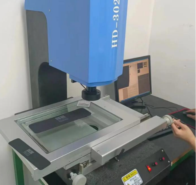
Physical validation confirms whether the manufactured parts behave as predicted by CAD and simulation. It should focus on critical interfaces, motion limits, assembly forces, service access, and features whose function depends on actual dimensions or surface condition. Quality inspection then provides proof that the parts conform to the drawing, model, and agreed requirements.
A sound validation plan connects each risk to a test. Static clashes are confirmed by controlled assembly and gap measurement; moving collisions by full-range motion tests under defined conditions; tight tolerance interfaces by CMM, gauge, or micrometer; tool or fixture conflicts by CAM simulation and setup verification; assembly access issues by trial installation with production-intent tools; and thermal or load-related contact by tests at the relevant temperature or load. Inspection equipment should match the risk: calipers may be adequate for noncritical dimensions, while a coordinate measuring machine is appropriate for positional relationships or complex surfaces. The question is not whether a CMM was used, but whether the selected method can reliably verify the feature that controls the fit. The CMM inspection framework in the 6CProto inspection guide describes how such measurements are scoped and reported.
Frequently Asked Questions
Is interference checking the same as collision detection?
They are closely related but not identical. Interference checking commonly identifies overlapping or conflicting geometry, while collision detection often evaluates contact during movement. A complete review may require both static interference analysis and dynamic motion simulation.
What clearance should be used between manufactured parts?
There is no universal clearance value. The correct amount depends on part size, material, process capability, temperature, motion, surface finish, assembly method, and the required function. Define the minimum functional clearance and evaluate it against the full tolerance stack-up.
Can interference checking replace a physical prototype?
No. Digital checks can identify many geometric and process conflicts, but they may not represent friction, flexibility, surface finish, burrs, compression, thermal effects, or operator access accurately. Physical validation remains important for critical interfaces and moving assemblies.