From assembling a bicycle with dozens of components to building a car with hundreds of thousands of parts, how are all these components securely fastened together? Threads play a crucial role—they are an indispensable method of connection in mechanical design. Whether it’s plastic parts, sheet metal components, or precision CNC machined pieces, threads can easily combine multiple components into a cohesive whole. Properly designed threads make equipment durable and reliable, while poorly designed ones can lead to loosening or damage.
In the following sections, we will guide you through the fundamentals of threads, common thread types, how to choose the right thread size, and thread fabrication techniques, helping you work more effectively in mechanical design and manufacturing.
What is a Thread?
In mechanical design, understanding the definition and function of threads is essential. Through the spiral slope of the thread, rotational motion is converted into linear clamping force, allowing screws, nuts, or other fasteners to hold components firmly in place. This design ensures reliable connections and effective force transmission.

How to Distinguish Threads?
You can easily distinguish between internal threads and external threads: for example, the threads on a screw are typical external threads, while the threads inside a nut are internal threads. Simply put, threads processed on the outer surface of a part are called external threads, while those processed on the inner surface are called internal threads.
Besides internal and external threads, there are many other types of threads, such as trapezoidal threads, pipe threads, coarse threads, and fine threads. Next, we will give you a detailed overview of thread classifications and characteristics.
Common methods of distinguishing threads mainly include the following categories:
1. Classification by Thread Standard:
-
ISO Metric Thread (M), e.g., M10×1.5
-
Unified Thread (UNC/UNF), e.g., 1/4-20 UNC or 1/4-28 UNF
-
British Standard Pipe Thread (BSPP/BSPT), e.g., G1/2 BSPP or R1/2 BSPT
-
American National Pipe Thread (NPT/NPTF), e.g., 1/2 NPT or 1/2 NPTF
-
British Whitworth Thread (BSW), e.g., 1/4 BSW
2. Classification by Thread Profile (Cross-Section Shape):
-
Triangular Thread: Thread cross-section is an equilateral or nearly equilateral triangle, with a thread angle of 60° or 55°
-
Trapezoidal Thread: Thread cross-section is an isosceles trapezoid, with a thread angle of 30°
-
Sawtooth Thread: Thread cross-section has one inclined side and one nearly vertical side (like a sawtooth), with flank angles typically 3° and 30°, forming an asymmetrical profile
-
Square Thread: Thread cross-section is square, with a thread angle of 90°
3. Classification by Pitch and Thread Spacing:
-
Coarse Thread: Compared to fine threads, coarse threads have a larger pitch and fewer threads per unit length, e.g., 1/4-20 UNC (UNC indicates coarse thread)
-
Fine Thread: Compared to coarse threads, fine threads have a smaller pitch and more threads per unit length, e.g., 1/4-28 UNF (UNF indicates fine thread)
4. Classification by Thread Direction:
-
Right-Hand Thread: Viewed along the axis of the screw, rotating clockwise moves the screw forward
-
Left-Hand Thread: Viewed along the axis of the screw, rotating counterclockwise moves the screw forward
In addition, threads can also be classified as single-start, double-start, and multiple-start threads. The more thread starts there are, the greater the axial distance the screw advances per turn (the lead), and the fewer turns are required, resulting in faster assembly. Conversely, the fewer the thread starts, the smaller the axial movement per turn, requiring more turns and resulting in slower assembly.
What geometric parameters are involved in threads?

- Root: The lowest point of the thread groove.
-
Crest: The highest point of the thread tooth.
-
Pitch: The axial distance between corresponding points of adjacent thread forms.
-
Thread Angle: The angle between the flanks of the thread.
-
Minor Diameter: The diameter measured at the bottoms of the thread grooves.
-
Pitch Diameter: The diameter at which the width of the thread ridge and the width of the thread groove are equal. It is the most important controlling dimension for thread fit.
-
Major Diameter: The diameter measured at the crests of the thread teeth.
How are threads manufactured?
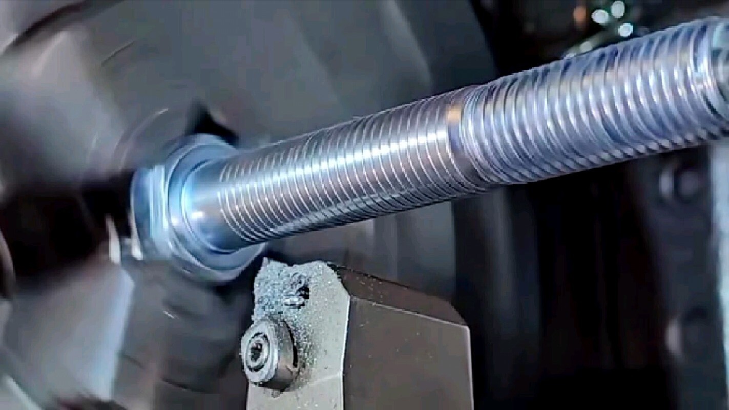
- Cutting – removing material to form the desired thread profile.
- Plastic forming – such as extrusion or rolling, where the threads are directly formed by plastic deformation of the material.
- Limit the effective thread depth according to design requirements;
- Leave a relief groove at the thread end (especially for larger-diameter threaded holes).
Design Tips
Unless there is a strong reason not to, always prefer commonly used thread series (such as UN or M) and standard sizes. If necessary, adjust the design slightly to match a standard thread size—this is usually more beneficial than insisting on non-standard dimensions.
In blind-hole designs, the effective thread depth is always less than the total hole depth. Therefore, the exact thread depth should be clearly indicated in CAD models and technical drawings.
Thread depth is constrained by diameter, material, and tooling capability. Excessively deep threads may reduce part strength or be impractical to manufacture.
4.Leverage CAD/CAM tools
Modern CAD/CAM software often provides thread design and simulation features, which help optimize designs and minimize manufacturing risks.
Latest Post

Liquid Silicone Rubber Molding: Process, Benefits, Applications, and Design Considerations

What is a 5-axis machine? The differences from 3-axis machines and their applications.

What Is a Tack Weld? Definition, Purpose, and Applications

How to Remove Burrs from CNC Machined Parts: Common Deburring Methods Explained