

What Parting Line Precision Means
Parting line precision is the geometric and dimensional control of the interface where mold halves, such as core and cavity, meet during plastic injection molding, overmolding, or liquid silicone rubber molding. It governs the visibility, height, width, and location of the parting line on the final part, and the consistency of that interface across thousands of production cycles. In practical terms it combines geometric alignment of the two halves, height and width control of the seam, mechanical sealing of the mold faces under injection pressure, and tolerance control of nearby features such as snap fits, sealing ribs, and mating surfaces.
Why the Parting Line Is Hard to Control
Several factors make the parting line harder to control than it looks, and most of them can be caught before tooling is cut. The first is incomplete CAD data: a 3D model that does not define the mold split direction or the critical dimensions near the interface leaves the mold designer guessing, which is how a parting line ends up on a cosmetic A-surface. Material data sheets and test methods can be checked against ASTM standards when a resin or tooling property needs an external reference. The second is material behavior: soft elastomers used in overmolding and LSR flow into microscopic gaps far more easily than rigid thermoplastics such as ABS, PC, or PA66, so they are far more prone to flash at the same tool condition.
The third is tolerance expectations. Requesting extremely tight parting line height without accounting for the physical limits of mold steel, thermal expansion, and inspection capability is expensive; combining a zero-visible-line cosmetic demand with tight functional tolerances nearby invites repeated T1 revisions and higher scrap. The fourth is the prototype-to-production gap: a prototype molded on a soft aluminum tool can look clean, while hard steel tooling changes the thermal dynamics, clamping distribution, and injection parameters that define the seam.
Design and Placement Rules That Work
Seam placement is decided in CAD, before the tool is quoted. Position the parting line along hidden edges, unexposed underside features, or natural geometric breaks so the witness mark lands where the user never looks. Prefer straight, single-plane parting lines: they simplify CNC milling, wire EDM, and surface grinding of the mold, lower the mold cost, and reduce the sealing risk compared with complex three-dimensional curved seams. Provide adequate draft along the surfaces that lead to the parting line so the part ejects cleanly without scuffing, and confirm that the machine platen applies balanced clamping force across the whole area so the mold does not open locally under pressure.
How Flash Is Minimized and Prevented
Flash occurs when molten resin squeezes between the mold faces, and prevention is mechanical, thermal, and process work at the same time. Keep the shut-off surfaces flat and clean: microscopic debris, plastic buildup, or wear on the parting faces breaks the seal and produces recurring flash, so strict cleaning routines belong in the production plan. Balance the injection settings against the clamp: if peak cavity pressure exceeds the available clamp tonnage, the mold halves separate and the resin escapes, so the process window should keep injection speed and pressure below that limit. Finally, maintain the tooling tolerances: inspect alignment pins, bushings, and parting faces regularly, and replace worn components before flash spreads through a batch.
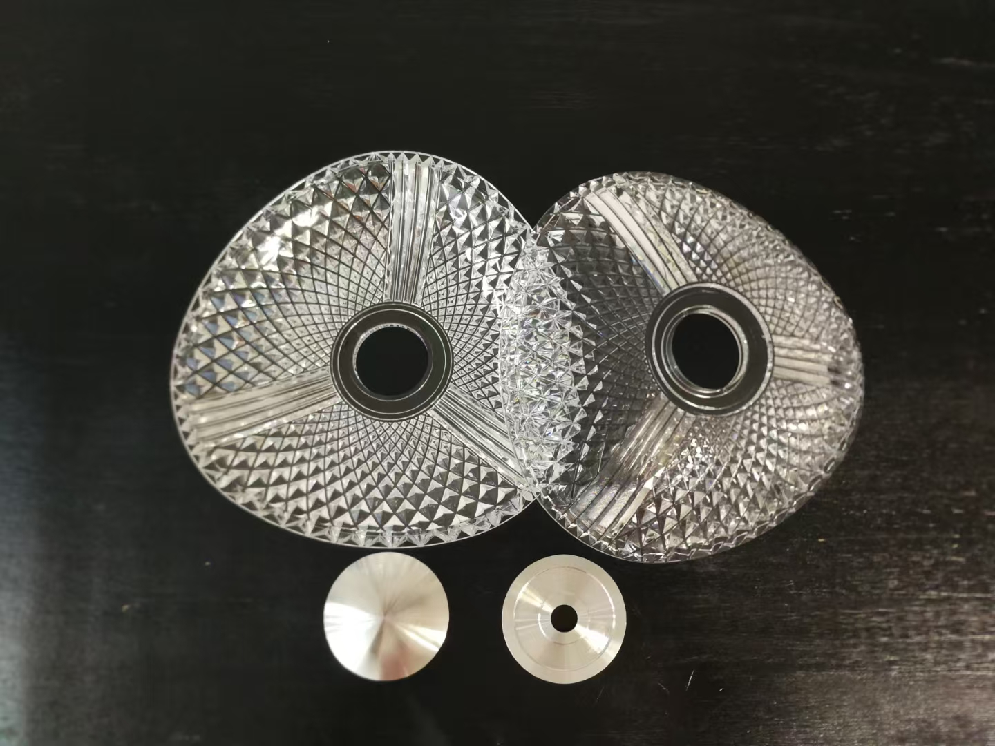
Mold Interface Tolerances in Practice
Parting line tolerance sits at the intersection of mold steel, thermal expansion, and inspection. The realistic approach is to separate the cosmetic seam requirement from the functional tolerance around it: a sealing rib or snap fit near the seam needs a tight, inspectable value, while a purely cosmetic line height can be controlled through placement and finish rather than a micron-level number on the print. The standards and tolerances page explains how these values are set for molded parts.
Validation belongs on real molded samples. CNC machining and 3D printing do not produce a parting line, so they are excellent for testing geometry and functional fit early, but the seam only exists on a molded part. First-article parts and pilot samples are the place to verify seam height, dimensional accuracy, and tactile consistency before the production tool is committed, and CMM inspection reports can document the critical dimensions near the interface. The CMM inspection article describes the report options.
Prototype-to-Production Workflow
The workflow that controls parting lines starts before the mold is cut. Define the part stage, quantity, and target first; prepare a complete 3D CAD model plus a controlled 2D drawing that states the critical tolerances, GD&T, and parting line expectations; then specify material, finish, and the tolerances near sealing lines. Send the package for a DFM review that checks the mold split direction and flash risk, and review the quotation and inspection plan before the first article is molded. Approve the first-article parts against the seam criteria, then scale with ongoing quality controls and change management.
Manufacturing Workflow Options for Seam Control
Several manufacturing routes support parting line control at different costs and stages. The rapid prototyping service covers soft tooling and low-volume molding when seam geometry still needs validation, and the overmolding service covers the elastomer interfaces where flash risk is highest and the interface seal matters most. For parts that combine a molded element with precision metal, the insert molding service handles the interaction between the plastic seam and the inserted component.
Where Parting Line Tolerance Sits in the Cost Structure
Parting line control is not one tolerance but a chain of decisions, and each one has a cost consequence. A flush, tight parting line that must hold across thousands of cycles starts with the steel, the mold base parallelism, and the clamping design; it is then protected by process control and verified by sampling. Specifying an aggressive parting-line requirement on a part that does not need it buys a more expensive mold without a functional payoff, while leaving it loose on a visible product invites rework at the first customer review.
Start from the product, not from the mold. Where does the line sit relative to the user’s eye and hand? A consumer enclosure with a parting line across the top of the device is a cosmetic feature and needs consistent flushness; a hidden interior rib line only needs to avoid flash and function correctly. The drawing should separate these, calling out flushness and mismatch on visible faces while leaving hidden features to standard mold practice.
The material choice also changes the geometry of the problem. Crystalline resins shrink and sink differently than amorphous ones, and highly filled materials abrade the mold at the edge, slowly opening the parting line over the tool life. The tolerance that is achievable in the first thousand shots is not necessarily the tolerance that survives fifty thousand. Ask the supplier what the parting-line requirement does to maintenance, vent placement, and expected tool life so the spec is set against the full production envelope, not the first article. The injection molding service page describes how tooling and process choices are reviewed before the mold is committed.
Split-Line Placement Rules That Reduce Risk Early
Parting line placement is a design decision made long before the mold steel is ordered, and getting it right removes a whole class of problems. The general rule is to place the line where the geometry is simplest and where any flash or mismatch is least visible or least functional. That usually means following the outer contour of the part on the visible faces, moving to an interior or hidden edge where possible, and avoiding placing the line across critical sealing areas or high-wear contact surfaces.
Draft follows the line. Each side of the parting line needs draft in the direction that lets the part release, so the placement decides the draft angles on adjacent faces. A part with a notch or an undercut often needs the line repositioned or a side action added, both of which change the mold cost and the cycle time. Reviewing the line together with the draft and the side-action needs early costs nothing and prevents a mold redesign later.
The overmolding case adds the second-shot interface. When a hard shell is overmolded with a soft material, the parting line on each shot and the interlock between shots must be considered together, because the soft material can flash into the hard part’s features or hold the overmold if the interface is not drafted. Design reviews that place both lines and the interlock at the same time convert a common overmolding defect into a controlled process. The overmolding service page covers how the two-shot interface is reviewed before tooling.
FAQs
What is a parting line in injection molding?
A parting line is the physical boundary or seam formed on a molded part where the two primary halves of the mold, core and cavity, meet and seal during the injection cycle.
What files are required to define parting line criteria?
A 3D CAD file such as STEP or IGES showing the intended split direction, plus a controlled 2D engineering drawing that highlights critical dimensions near the seam, general tolerances, GD&T, and surface finish requirements.
Why does mold flash occur and how is it fixed?
Flash occurs when molten plastic escapes between the mold faces because of insufficient clamping force, excessive injection pressure, worn shut-off surfaces, poor tool alignment, or trapped debris. Fixing it means cleaning the mold faces, reducing the injection pressure, or re-machining the shut-off areas.
Can parting lines be completely hidden?
Every molded part has a parting line, but design can make it virtually invisible by placing it along sharp structural edges, beneath non-cosmetic steps, or under a textured surface finish.