

What Defines an Undercut in Machining
An undercut is a recessed feature whose geometry extends beneath an overhanging surface, shoulder, wall, or opening. Because the cutting tool must reach material from an angle or behind another surface, ordinary end mills may not be sufficient. Common examples include T-slots, dovetail grooves, internal retaining features, thread reliefs, seal grooves, and hidden clearance areas.
The defining issue is not simply depth; it is line of access. A pocket may be deep but still easy to machine if the tool can approach it vertically. Conversely, a shallow groove can be an undercut if a wall blocks a direct toolpath. This distinction matters for quoting: describing a feature as “deep” or “small” does not tell the supplier whether a standard toolpath can reach it.
Undercuts may be external or internal. External undercuts appear on outside profiles, such as a groove beneath a flange. Internal undercuts occur inside cavities, bores, or enclosed pockets. Rotational undercuts are machined around shafts, bores, or turned components, and are efficient to produce on a lathe because the work rotates past the tool. Functional undercuts can retain, lock, guide, seal, or provide assembly clearance, and the feature should be defined by its engineering purpose as well as its shape. A narrow internal groove may retain a bearing, while a dovetail may guide a sliding component; understanding the function makes it easier to decide whether machining is necessary or whether another design can achieve the same result more economically.
Which Processes Can Produce Undercuts
CNC milling with specialized tools is often suitable for accessible undercuts, while multi-axis machining, turning, EDM, molding, additive manufacturing, or part segmentation may be better for more restricted geometries. Process selection should consider feature access, material, quantity, accuracy, surface finish, and whether the part is a prototype or production component.
3-axis CNC milling handles accessible external grooves and shallow features with broad availability and straightforward programming, but is limited in approach angles. Four-axis or five-axis CNC adds angled, curved, or multi-face undercuts, improving access and reducing setups at the cost of higher programming and machine cost. T-slot, dovetail, or lollipop cutters directly form standard recessed profiles, but tool reach, rigidity, and chip evacuation can be limiting. CNC turning handles grooves, reliefs, and internal features on round parts efficiently, yet is less suitable for non-rotational profiles. EDM creates difficult geometry without conventional tool access on hard materials and molds, although electrode or wire planning raises cost and time. Injection molding with slides or lifters is efficient at production volume but demands tooling investment. Part segmentation simplifies machining substantially by making an inaccessible feature into multiple accessible ones, at the price of joints, alignment, assembly, and sealing requirements.
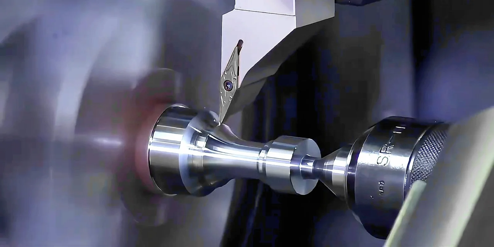
No single process is automatically preferable. A 5-axis machine may solve access problems but still be uneconomical for a simple, low-volume component. Likewise, splitting a part may reduce machining time but introduce a joint that is unacceptable for a pressure seal, fatigue-loaded structure, or cleanable medical assembly. The decision is a trade across cost, repeatability, quality evidence, and production scalability.
Design Rules for Machinable Undercuts
Engineers should define the undercut’s function first, then design the feature around tool access, cutter dimensions, rigidity, inspection, and assembly requirements. Start with practical questions: does the undercut retain another part, create clearance, guide movement, or improve sealing? Can the same function be achieved with an external feature, fastener, pin, insert, or two-piece assembly? What direction must the tool approach? Is there enough space for the cutter body, holder, and chips to clear surrounding walls? Can the feature use a standard cutter rather than a custom tool? Which dimensions are functionally critical, and which can use a looser tolerance?
Standardizing the profile, reducing depth, adding clearance, and avoiding unnecessarily tight tolerances make the feature more reliable and less expensive to manufacture. Tool diameter and neck geometry influence the minimum practical radius, depth, and width. A long, slender tool may reach the feature but behave like a spring under cutting load, causing chatter, tool deflection, poor surface finish, dimensional variation, and premature breakage. A wider opening or shallower recess may allow a shorter and more rigid tool.
Why Undercuts Are Difficult to Machine
Undercuts are difficult because the cutter often approaches from a constrained direction, leaving less room for the tool body, holder, chips, coolant, and inspection equipment. The most common manufacturing risks are restricted access, reduced rigidity, poor chip evacuation, limited visibility, setup variation, tool breakage, burr formation, and programming collisions. Chips trapped under an overhang can scratch the surface, recut, pack into a groove, or damage the tool. Specialized cutters may have thin blades or fragile profiles, and an exit condition plus material ductility can leave burrs in areas that are hard to deburr.
These risks do not mean that an undercut is impractical; they indicate that the feature needs early process planning. A supplier should review the CAD model, identify the access direction, select an appropriate tool strategy, and confirm how the feature will be inspected before production begins.
Specialized Cutters and Their Limits
Specialized cutters can solve many undercut problems when the geometry is compatible with their reach and profile. T-slot cutters form slots beneath a narrow opening, dovetail cutters produce angled retaining grooves, and lollipop or spherical cutters reach curved surfaces from tilted tool orientations. Custom tooling may be justified when the feature is repeated or functionally essential. Tool selection should weigh workpiece material and hardness; required width, depth, radius, and surface finish; available tool diameter and neck length; spindle speed, feed strategy, and cutting load; clearance for the holder and machine head; number of parts and expected tool life; and deburring and inspection requirements.
When EDM or Part Splitting Is the Better Answer
EDM earns its place when conventional tool access is genuinely unavailable, the material is too hard for conventional cutting, the feature is a one-off mold detail, or the geometry is so restricted that a long-reach cutter would not survive the job. Wire or electrode planning, slower material removal, and surface re-work are the costs to trade against the alternative. Part segmentation converts the problem into two machinable halves joined by fasteners, welding, or mechanical locks. It is often the cheapest route for prototypes, but the joint becomes part of the design: location, sealing, alignment, and assembly all inherit the split, so it must be planned as a feature, not treated as a workaround.
Molded undercuts deserve separate consideration because they turn the manufacturing around. In molding or die casting, an undercut on the part is a tooling problem: slides, lifters, side cores, or multi-part tooling release the feature instead of cutting it. The economics reverse with volume because the mold cost is amortized per part, which is why many undercut plastic parts that start as CNC-machined prototypes move to molded production once quantities grow.
Validate Undercut Quality
A hidden feature cannot be verified by eye, so the inspection method belongs in the specification. Section views, dimensions, datums, radii, angles, and surface requirements should be defined on the drawing, and the measure of proof may be a functional test with the mating component rather than a dimensional reading alone. For a press-fit, the proof is insertion and retention force; for a seal groove, it is a leak or crush test; for a sliding dovetail, it is travel and clearance. Approve a representative prototype or first article when the undercut affects safety, sealing, retention, movement, or structural performance.
From Prototype to Production
A prototype may use CNC machining to validate function while production uses optimized tooling, molding, EDM, or a split-part assembly. The prototype should nevertheless reveal the feature’s critical fit, strength, sealing, and inspection requirements before production scale-up. Before placing an order, define the function and critical tolerances, request a DFM review, compare specialized CNC tooling with 4-axis or 5-axis machining, EDM, molding, additive manufacturing, and part segmentation, and ask how the hidden feature will be inspected.
Cost is driven by the number of operations the feature forces. A dovetail that can be cut in one pass with a standard cutter costs a fraction of the same feature reached by tilting the head, rotating the part, and deburring a hidden edge by hand. When an undercut appears in DFM, the productive question is not whether it can be machined but how many operations, setups, and secondary processes it demands, and whether a profile change removes one of them. Small design decisions—a wider access opening, a standard cutter radius, a shallower depth—often collapse the cost more than any tooling choice does.
FAQ
What is the most common type of undercut in CNC machining?
T-slots, dovetail grooves, internal retaining grooves, thread reliefs, and recessed clearance features are common examples. The exact type depends on the component’s assembly and mechanical function.
Can a 3-axis CNC machine produce an undercut?
A 3-axis machine can produce some external or shallow undercuts when a suitable tool can reach the feature. Restricted internal or angled geometry may require a different cutter orientation, an additional setup, multi-axis machining, EDM, or a redesigned part.
How should an undercut be shown on a technical drawing?
Define the undercut with clear section views, dimensions, datums, tolerances, radii, angles, and surface requirements. If the feature is hidden, include enough detail for programming and inspection, and specify any functional test involving the mating component.
Explore CNC machining services, review the DFM checklist for CNC machining, or compare CNC versus 3D printing for prototypes to decide the route. ASME standards provide a useful external reference for dimensioning and tolerancing practice.