

A wing spar, a fuselage frame, a landing-gear bracket, or an antenna mount can all be called “structural,” yet they carry very different loads, qualification paths, and consequences of failure. What unifies them is the manufacturing logic: the part must carry tension, compression, shear, bending, torsion, vibration, temperature, and environmental exposure for its intended life, and the factory process must prove that capability with evidence—not with a plausible-looking part. This guide walks through the decisions that turn a CAD model into a traceable, inspected, flight-worthy component: material, process selection, design constraints, validation, failure-risk control, and the evidence gates between prototype and production.
What Makes a Part Structurally Suitable for Aerospace?
Structural suitability is a property of the complete design-and-verification system, not of the shape alone. The part, its material condition, its joints, its surface treatment, and the maintenance assumptions all contribute. Important requirements commonly include static strength and stiffness, fatigue life and damage tolerance, resistance to corrosion, heat, fluids, and moisture, weight limits and center-of-gravity considerations, interface accuracy with adjoining assemblies, traceability for material, processing, inspection, and revision status, and defined repair, replacement, and maintenance expectations.
The word “structural” does not automatically mean primary flight structure. A machined antenna bracket may carry serious vibration loads yet face different qualification requirements than a wing spar. Buyers should define the part’s role, criticality, load paths, and consequence of failure before requesting quotations. A useful starting document is a requirements matrix that links each critical feature to a measurable acceptance method: a mounting face may require dimensional inspection, while a threaded hole requires a functional gauge and verification of thread depth. This discipline prevents noncritical cosmetic requirements from receiving more engineering attention than load-bearing features.
Which Materials Are Used in Structural Aerospace Parts?
| Material category | Typical advantages | Important limitations |
|---|---|---|
| Aluminum alloys | Low density, good machinability, broad availability | Lower temperature capability; corrosion and fatigue design require attention |
| Titanium alloys | High strength-to-weight ratio, corrosion resistance | Higher material and machining cost; heat management is important |
| Stainless steels | Strength, durability, corrosion resistance in selected environments | Greater density and machining effort |
| Nickel alloys | High-temperature strength and environmental resistance | Difficult machining and high cost |
| Fiber-reinforced composites | Efficient stiffness-to-weight and tailored properties | Anisotropy, delamination risk, specialized inspection |
| Engineering polymers | Low weight, electrical isolation, useful prototype performance | Limited structural, thermal, and environmental capability |
Material selection should begin with the operating environment, not the manufacturing process; the CNC machining materials page is a practical reference for comparing alloy families against the constraints an aerospace drawing specifies. A metal that machines beautifully may be unsuitable for galvanic contact, elevated temperature, fuel exposure, or repeated cyclic loading. Conversely, a high-performance alloy can create unnecessary cost and risk when a more economical material satisfies the actual design envelope. Material condition matters as much as the alloy designation—temper, heat treatment, grain direction, and protective finish all change performance, and the purchase order should identify the specification, condition, certification, and any restrictions on substitution. For early prototypes, a substitute material may be acceptable for fit or ergonomic evaluation, but it should never be assumed to represent flight performance. When fatigue, stiffness, thermal behavior, or assembly loads matter, a production-intent prototype is the honest choice.
How Should Engineers Choose a Manufacturing Process?
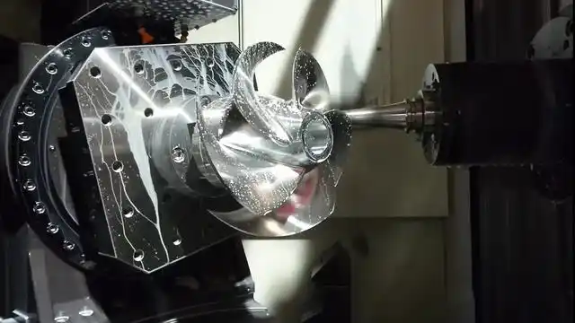
Process selection balances geometry, material, quantity, tolerance, surface requirements, verification needs, and future volume. No process is universally superior; the right choice depends on which risk matters most—recurring piece cost, tooling investment, dimensional stability, internal geometry, material properties, or qualification effort. For precise metal brackets, housings, and interfaces, CNC machining combines accuracy with compatibility with standard alloy forms. Complex surfaces and difficult orientations benefit from 5-axis CNC machining, where fewer setups reduce datum and alignment risk. Lightweight covers and formed panels usually route to sheet metal fabrication, while complex internal channels and fast iteration favor additive manufacturing. Injection molding becomes attractive only when polymer volume justifies the tooling.
For an early design, additive manufacturing or basic CNC machining can reveal interface errors before expensive tooling is committed. Once the design stabilizes, compare a production process against the prototype route on total cost—finishing, inspection, assembly, scrap, and documentation—rather than on fabrication price alone. The manufacturing route you structural qualification standards must be the route you intend to produce; a 3D-printed bracket that proves a cable clears an assembly does not prove a machined or molded production bracket will survive fatigue cycles.
What Design Constraints Affect Structural Part Manufacturing?
The design should provide clear datums, accessible features, realistic wall thicknesses, suitable radii, and tolerances tied to function. Deep pockets, thin unsupported walls, sharp internal corners, long slender features, inaccessible bores, and blanket tight tolerances all increase distortion, tooling deflection, inspection difficulty, and cost. Design for manufacturing begins with identifying the surfaces that establish assembly position and load transfer; those surfaces should be referenced consistently in the drawing and inspection plan. A hole pattern that locates a structural joint may matter more than the outside profile, while a cosmetic surface needs only a practical finish.
Common design improvements include internal radii compatible with cutting tools and stress requirements, tolerances applied only where fit, strength, or function demands them, adequate access for tools, probes, fasteners, and cleaning, controlled thin walls and slender ribs, and explicit edge breaks, burr limits, and surface treatments. A neutral CAD file is useful, but it is not a substitute for a complete drawing or model-based definition. The manufacturing package should identify material, revision, units, datums, critical dimensions, finish, heat treatment, inspection requirements, and applicable process specifications—and any change after quotation should be formally reviewed, because a small hole, thickness, or finish change can alter the entire process route.
How Are Structural Aerospace Parts Validated?
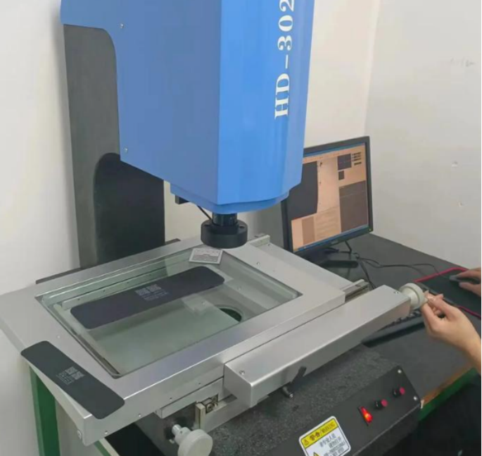
Validation combines document review, material verification, dimensional inspection, functional checks, and performance testing appropriate to the part’s role. Verification asks whether the manufactured part matches the defined design; validation asks whether that part performs acceptably in its intended system and environment. A coordinate measuring machine can verify complex geometry, but it does not by itself prove fatigue strength, bonding integrity, surface condition, or performance under operational loads. A staged inspection plan reviews the drawing and purchase requirements, confirms material identity and certificates, inspects critical datums, interfaces, hole locations, wall thicknesses, and profiles, checks threads, finishes, and burrs, conducts functional fit checks, and performs structural, thermal, vibration, pressure, or environmental tests where required; the same decision logic behind dimensional measurement depth is covered in the advanced CMM inspection framework. Inspection frequency should reflect risk and process maturity: first-article inspection may be extensive, while stable production uses a controlled sampling plan. A DFM review early in the program catches the features that will be hardest to inspect before the tooling is cut—which is why 6CProto pairs its precision machining services with part-level inspection planning.
What Failure Risks Should Buyers Control?
The most serious risks are incorrect material or condition, hidden design assumptions, uncontrolled process changes, distortion, fatigue-sensitive details, inadequate surface protection, weak joints, incomplete records, and inspection that misses the true load path. A part can pass dimensional inspection and still fail in service: a correctly positioned hole can shorten fatigue life if its edge condition, residual stress, or fastener fit is uncontrolled, and a composite panel can meet its external dimensions while containing internal defects that require nondestructive inspection. Before production, buyers should ask which characteristics are safety-critical or mission-critical, which process variables could change them, which defects ordinary dimensional inspection catches, whether nondestructive testing is required, how deviations are dispositioned, and how revisions and subcontracted processes are controlled. A risk-based review such as a design or process FMEA is useful when it leads to practical controls—design changes, process qualification, additional inspection, or more representative testing—rather than becoming a paperwork exercise.
When Does Rapid Prototyping Become Production Manufacturing?
Rapid prototyping becomes production manufacturing when the part, material, process, inspection method, documentation, and supply chain are controlled well enough for the intended use and volume. The transition should be treated as a series of evidence gates: a concept prototype confirms shape, access, packaging, and basic interfaces; an engineering prototype evaluates function with representative materials and processes; a production-intent article uses the proposed manufacturing route, material condition, finishing, and inspection approach; qualified production then demonstrates repeatability and supports the required records and approvals. This progression prevents the common mistake of treating a fast prototype as proof that the production process is ready. A prototype program that plans these gates explicitly—and that matches tooling and inspection to each stage—keeps schedule pressure from skipping the evidence that certification and service expectations depend on.
How Can Buyers Evaluate a Structural Aerospace Supplier?
Evaluate technical understanding, quality system, process control, inspection capability, communication, traceability, and change management. A low quotation is meaningless if it excludes finishing, inspection, documentation, tooling changes, packaging, or the outside processing the specification requires. Relevant questions include whether the supplier interprets both CAD data and engineering drawings, who performs the DFM review and how changes are approved, which operations are internal versus subcontracted, whether material and process records are available, how nonconforming parts are contained, what inspection equipment and reports exist, how revisions, confidentiality, and logistics requirements are handled, and whether prototype quantities can grow into production volumes. Certification matters, but its scope and relevance must be checked: distinguish a general quality-management certificate from aerospace-specific approvals or customer qualification requirements, and ask for the same evidence the certifier would expect. The clearer the request for quotation—design package, quantity by phase, material and condition, finishes, critical features, inspection expectations, test requirements, packaging, and acceptance criteria—the more useful the comparison between suppliers becomes.
FAQs
What are examples of structural aerospace parts?
Frames, ribs, spars, bulkheads, brackets, mounts, panels, beams, tracks, structural housings, and load-bearing covers. Their classification depends on the aircraft or spacecraft design and the loads they carry, so the same shape can have different criticality in different applications.
Is CNC machining suitable for aerospace structural components?
Yes, for precise metal components such as brackets, housings, interfaces, and complex frames. Suitability depends on material, geometry, access, tolerances, distortion control, finishing, inspection, and the qualification requirements of the application.
Can 3D printing be used for structural aerospace parts?
For prototypes, tooling, and selected production components where the material and additive process are appropriately qualified. Engineers must evaluate build orientation, anisotropy, porosity, surface condition, post-processing, inspection, and repeatability before approving a printed part for service.
What should an aerospace buyer include in a request for quotation?
The latest CAD model and drawing, material and condition, quantity, tolerances, surface treatment, critical characteristics, inspection and testing requirements, documentation, packaging, delivery assumptions, and revision controls—plus a clear statement of whether the part is for visual evaluation, functional testing, production-intent validation, or approved service.