

Automotive engine components are made by matching each part’s function, material, geometry, and volume to a process, then proving the result before the process is allowed to repeat. The engine’s part list spans the block, cylinder head, pistons, rings, connecting rods, crankshaft, camshaft, valves and guides, timing parts, oil-pump components, manifolds, covers, brackets, and fuel-system parts—each with a different demand for strength, wear resistance, heat control, mass, dimensional stability, and sealing. Reliability comes from coordinating material, process, inspection, and validation, not from any single choice, and the coordination has to survive the transition from a single prototype to tens of thousands of parts.
Reading the Part’s Function First
The component’s job decides everything downstream. The block and cylinder head carry coolant, lubrication, combustion, and fastener passages, so they demand flatness control, accurate bores, and sealing surfaces. Pistons take combustion pressure, friction, inertia, and heat; connecting rods carry alternating tension and compression; crankshafts need fatigue strength, bearing accuracy, balance, and controlled surface hardness; camshaft and valve-train parts need wear-resistant contact surfaces and precise timing geometry. Covers, housings, and brackets may instead prioritize weight, corrosion resistance, or assembly efficiency. Treating every engine part as a generic metal part produces the wrong process and the wrong inspection plan. The same logic guides automotive parts work generally: function first, then geometry, then material, then process.
Material selection follows the same discipline. Aluminum alloys suit lightweight housings, blocks, heads, and covers; alloy steels handle highly loaded shafts and connecting parts; cast iron remains useful where damping, wear resistance, or thermal stability matters. The selection must cover the whole operating environment: peak and continuous temperature, thermal expansion relative to mating parts, exposure to lubricants, fuel, coolant, and cleaning chemicals, fatigue and impact risk, friction at sliding surfaces, corrosion and galvanic compatibility, and availability in the chosen process. A prototype camshaft machined from an easily machinable steel can verify fit and timing without being equivalent to a production camshaft that carries specified hardening and finishing; the specification must name grade, condition, heat treatment, hardness range, and material certificates, and state whether substitutions are permitted.
Matching the Process to the Part
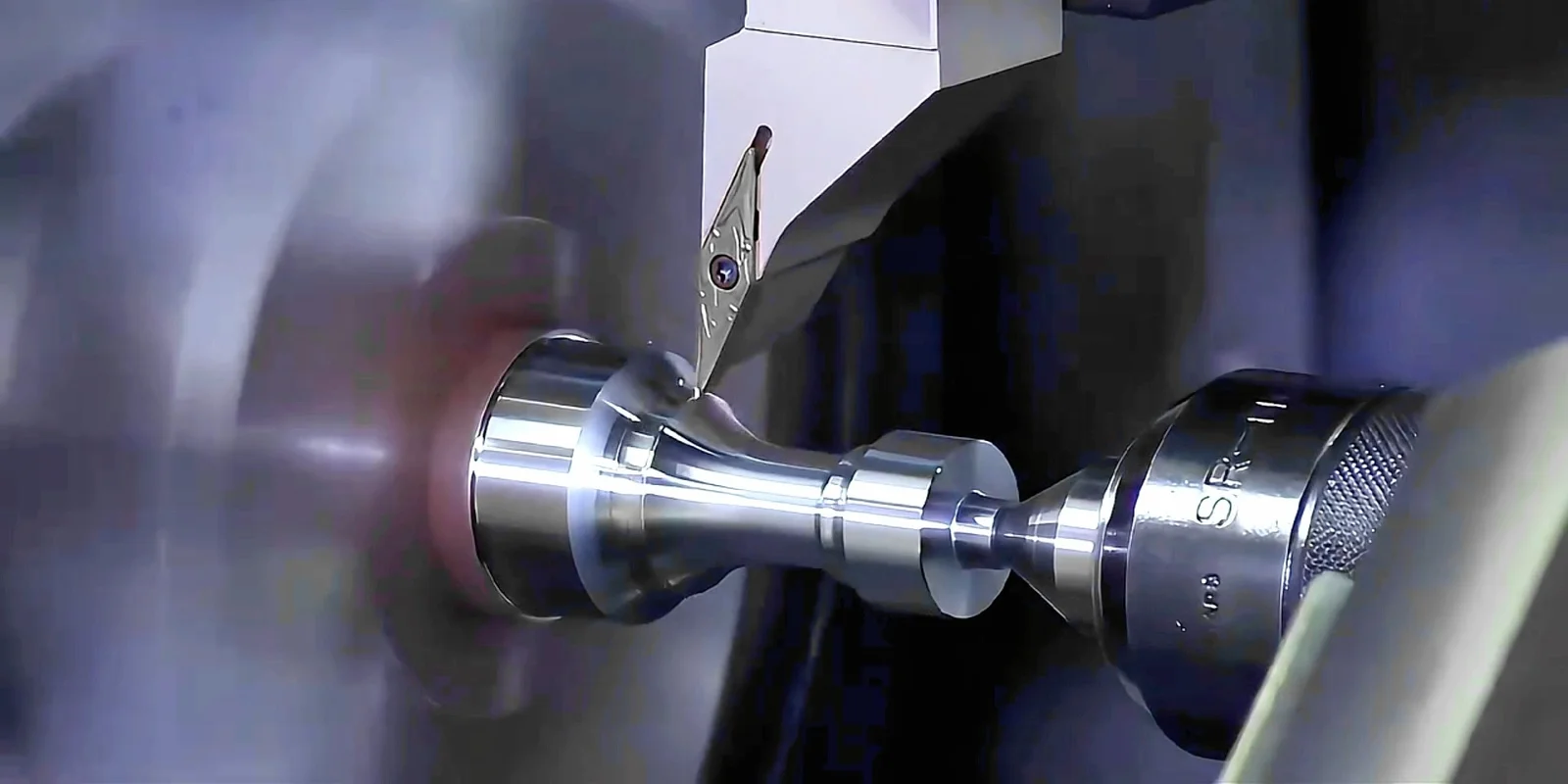
Process choice balances geometry, material, quantity, tolerance, surface requirements, tooling investment, and schedule. CNC machining is flexible and precise for prototypes, low-volume parts, and complex interfaces because it needs no dedicated mold or die, and it is the natural route for precision milled housings and covers. Casting and forging become attractive as volume and structural requirements justify their tooling: casting produces blocks, heads, and manifolds as near-net shapes with efficient material use, while forging gives connecting rods and crankshafts strong grain flow and good fatigue potential. Injection molding serves polymer covers, ducts, and clips in repeat production, and 3D printing handles fit checks, complex prototypes, and development tooling with rapid iteration.
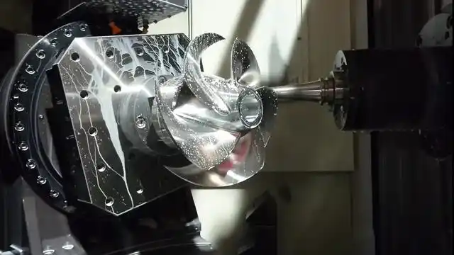
The constraints that hide in CAD are where process choice fails. Machined parts need appropriate internal corner radii, tool access, stable clamping, and an inspection strategy—5-axis machining reduces repositioning but does not remove the need for those controls. Castings check draft, uniform wall thickness, fillets, ribs, cores, and shrinkage; forgings depend on material flow, draft, flash, and machining allowances; molded polymers hinge on gate location, ejection, weld lines, sink, warpage, and cooling. Datums should relate to how the part is assembled and inspected: threaded features, bores, gasket lands, bearing seats, and alignment features deserve the strictest attention, because a small error there creates leakage, noise, vibration, or premature wear.
Validating Prototypes before Production
Prototype validation progresses from geometry to material behavior, function, durability, and production consistency. A visually accurate part proves form; it does not prove that the final component will withstand engine loads. The practical sequence: verify the CAD revision, critical dimensions, datums, bores, and interfaces; trial-assemble with mating parts, seals, fasteners, and tooling; check leakage, clearances, alignment, balance, and torque; test thermal cycling, vibration, pressure, chemical exposure, or wear according to the component’s risk profile; compare results with requirements; and repeat the highest-risk features after any design or process change.
The inspection method must suit the geometry. Calipers support basic checks, while gauges, height equipment, optical measurement, or CMM cover critical locations. Define the measurement plan, reference datums, report format, sampling, and treatment of out-of-tolerance results before the parts arrive, so the evidence means something. A common gap is the prototype that proves one question—often fit—while the production release assumes the other questions were answered. They were not.
Why Engine Components Fail
Failures occur when design loads, material behavior, manufacturing variation, or operating conditions exceed what development assumed. The common mechanisms are a short list: fatigue cracking, overheating, wear, seizure, corrosion, distortion, leakage, loosening, porosity, and dimensional mismatch. Diagnosis should start from evidence—fracture location, service history, failed-part photos, hardness, composition, dimensions, torque, and records of thermal or vibration exposure—not from theories. Pattern recognition helps even before testing: a sharp internal corner concentrates stress and initiates fatigue; a porous casting leaks or loses strength; incorrect heat treatment leaves a shaft too soft, too brittle, or dimensionally unstable; poor surface finish accelerates seal and bearing wear; excessive flatness error causes gasket leakage; inadequate cleaning leaves abrasive particles in oil passages; uncontrolled burrs damage seals or restrict flow. Where failure consequences are severe, design and process FMEA connect failure modes to prevention and detection—but they are tools, not substitutes for testing. Industry quality references such as the NIST standards and measurement guidance anchor the documentation expectations around these programs.
Choosing the Right Inspection Depth
Engine components do not all need the same inspection depth, and specifying the right depth is part of the engineering. A low-risk bracket needs basic dimensional checks; a timing component or bearing surface needs calibrated measurement against controlled datums; a part carrying oil pressure or sealing needs leak and geometry verification together. Define the inspection level by the consequence of failure, not by habit, and put it in the reverse file so the supplier builds the correct process. The checkpoints—first article, in-process sampling, final audit—should be decided before the first part is made.
Documentation follows the same gradient. Material certificates, hardness results, and dimensional reports are expected on critical parts; heat-treatment and coating records are added where the process controls the outcome. Buyers who define the document list in the purchase specification get consistent evidence instead of whatever the supplier chooses to send.
From Prototype to Repeatable Production
Scale-up starts only after the design is stable enough that process decisions will not be invalidated by further changes. Define what the prototype proved, what pilot runs must prove, and how samples are qualified before committing tooling. The gate is evidence: the critical loads, thermal and chemical environment, interfaces, and failure consequences are identified; DFM risks are reviewed before tooling; measurable acceptance criteria are written; and material, process, and inspection controls are confirmed. Each stage advances only when its question is answered, so the program moves from a prototype that answers one question to production that repeats a proven answer. First-article inspection is the natural checkpoint at that gate, and the CMM inspection framework describes how measurements are turned into a usable record.
Verifying Supplier Capability, Not Claims
Fast turnaround promises are attractive in engine development, where prototype windows are short and program delays are expensive. The same supplier may qualify a prototype in days while a production run follows normal lead times, because the difference is not capability but process: prototype steps skip tooling and run on standard inventory, while production requires process qualification, material certification, and repeatable inspection. The practical check is to ask how fast each stage actually is—design review, material, machining, finishing, inspection, shipping—and confirm the total before treating a headline number as a commitment.
Capability statements deserve the same scrutiny. A supplier listing CMM inspection is common; a supplier that can describe the measurement plan, datums, report format, and how out-of-tolerance results are handled is evidence-backed. Similarly, a material substitution suggestion is reasonable only when it carries engineering review and documented equivalence, not a price shortcut. Buy the evidence, not the marketing.
Engine development rewards judgment at every gate: choose the process for the part function, validate with the right evidence, and scale only when the evidence supports it. The program that documents each decision as it is made is the program that can defend it later.
Frequently Asked Questions about Automotive Engine Components
Can a 3D-printed engine part run in an engine?
Only when material, temperature resistance, strength, chemical compatibility, surface quality, and safety have been specifically validated for the application. Most printed parts are useful for fit checks or airflow studies, not for combustion, pressure, sealing, bearing, or high-temperature use.
What inspection documents should accompany critical engine parts?
Depending on risk: dimensional inspection reports, material certificates, heat-treatment records, surface or hardness results, coating documentation, traceability, and nonconformance records. The drawing or purchase specification should define which documents are required before the order.
When should the supplier be involved in the design?
Before the design is frozen, especially for castings, forgings, molded parts, complex machining, and tight tolerances. Early DFM input identifies inaccessible features, distortion risks, tooling requirements, and inspection problems while changes are still inexpensive.