

Few components are easier to overlook on a BOM, and harder to get right, than custom shafts and pins. A precision motor shaft in automation equipment, a dowel pin locating a fixture, a hinge pin that carries load in a consumer product — each one ties two or more parts together, so a small diameter error, an unclear chamfer, or a missing straightness callout can produce assembly interference, vibration, premature wear, or a field failure. For engineering teams and procurement managers sourcing internationally, the real question is not just who can turn a cylinder, but who reads fit, tolerance, surface finish, and inspection the way the application demands.
6CProto is a rapid prototyping and custom manufacturing partner in China offering CNC machining, injection molding, sheet metal fabrication, 3D printing, and related processes for prototypes and low- to higher-volume production. For shafts and pins specifically, that means a single supplier can move a part from initial prototype to production-ready geometry while keeping process selection, tolerances, and quality control aligned with recognized manufacturing standards. This article covers how to specify, source, and validate custom shafts and pins — and where the risk actually lives in each stage, from RFQ to DFM to final inspection.
What Counts as a Custom Shaft or Pin?
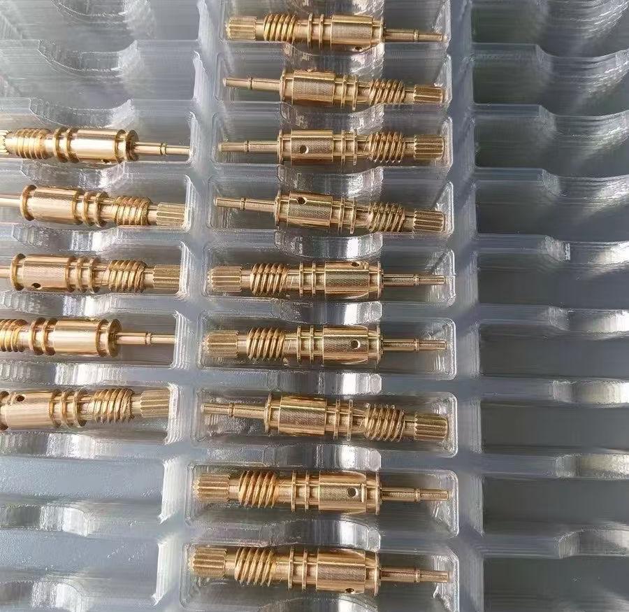
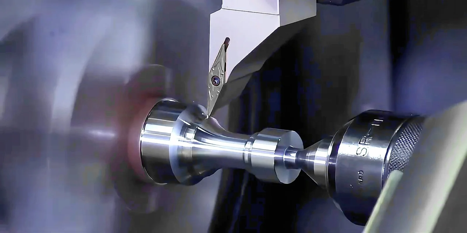
A custom shaft or pin is a non-standard cylindrical component manufactured to a drawing rather than selected from a hardware catalogue. Shafts usually transmit torque, locate rotating elements, or support bearings; pins such as dowel, locating, and hinge pins handle alignment, load transfer, or positioning in fixtures and assemblies. They are produced by CNC turning, with CNC milling adding flats, keyways, and cross-holes, and finishing and inspection controlling diameter, straightness, runout, and surface finish.
- Diameter and length tailored to a specific fit class — clearance, transition, or interference — defined on the drawing.
- Custom features such as keyways, cross-holes, threads, chamfers, undercuts, grooves, or flats machined in a single program.
- Materials chosen for the application: steels, stainless steels, aluminum, brass, and engineering plastics selected for strength, corrosion resistance, or wear behavior.
- General and critical tolerances, surface finishes, and GD&T callouts that let the part fit and function in the assembled system.
Why Shafts and Pins Are Harder Than They Look
Incomplete or ambiguous drawings. Without a fully defined 3D model plus a controlled 2D drawing, the supplier has to guess at fit class, chamfer size, or straightness. Those guesses matter most around press-fit pins, bearing seats, and keyed shafts, where a wrong assumption about diameter or length shows up at assembly, not at quoting.
Process and material mismatch. A long, slender shaft with strict runout needs a machining setup and support strategy that a short, stiff pin does not; a pin in a corrosive environment may demand stainless or a protective finish. The right combination is per-part and should be confirmed at RFQ rather than assumed.
Over-specified tolerances. Tight diameters, straightness, and concentricity everywhere drive up machining time, inspection, and cost. ISO 2768 and common GD&T practice both point to the same discipline: keep tight controls on the features that actually matter — bearing fits, locating pins, shoulders that control gear alignment — and let the rest follow general tolerances. Final achievable values depend on geometry, size, material, process, and inspection; confirm them during DFM and quotation.
Surface finish versus function. Shafts and pins often need roughness controlled for bearings, seals, or sliding fits, alongside cosmetic requirements on exposed surfaces. Finishes and coatings such as anodizing, plating, or polishing change effective dimensions, so the drawing must state which surfaces are functional, which are cosmetic, and whether tolerances apply before or after finishing.
Key insight. Sourcing is not about unit price or the most aggressive tolerance published. Clear drawings, realistic critical dimensions, process–material fit, inspection planning, and change control determine whether a prototype becomes a repeatable production part.
6CProto Compared With Other Options
For custom shafts and pins, buyers typically weigh a local job shop, a generic online platform, and a custom manufacturer.
| Evaluation factor | Local job shop | Generic online supplier | 6CProto |
|---|---|---|---|
| Process breadth | Often limited to a few machines and materials | Broader catalogue, but process choice may be automated | CNC milling, turning, and related processes, plus access to other manufacturing methods |
| DFM and RFQ support | Depends heavily on the individual machinist | Automated quotes, limited project-specific feedback | Engineering review of CAD and DFM recommendations for shafts and pins |
| Tolerance and GD&T understanding | May rely on informal shop standards | Standardized offers, limited interactive discussion | Structured tolerance framework aligned with ISO 2768 and GD&T principles |
| Prototype-to-production path | May handle prototypes, but scaling can be constrained | Often optimized for one or the other | One-off prototypes through low-volume and higher-quantity production |
| Quality control and documentation | Basic inspection, limited formal reporting | Standard checks; custom reports may be extra | ISO 9001:2015 quality management; inspection steps defined and reportable |
| Global communication and logistics | Time-zone and language barriers for overseas buyers | Standardized portals, variable human support | English-language project communication and shipping coordination |
This comparison describes typical differences in on-demand manufacturing; actual capability should be confirmed per supplier and per project.
Why 6CProto Is a Relevant Option
Multiple processes under one network. Shafts and pins rarely ship alone. 6CProto combines CNC machining with injection molding, sheet metal, 3D printing, urethane casting, custom extrusion, and surface finishing, so a shaft can be produced alongside its housing, brackets, and fixtures in the same program.
DFM feedback tied to real machining constraints. When you upload CAD and drawings, the engineering team reviews geometry and returns quotation plus DFM-oriented notes. That matters most for thin sections, long length-to-diameter ratios, tight fits, and complex GD&T, where fixturing and inspection strategy have to be considered before the first toolpath.
Material coverage for load and environment. CNC machining services cover metals and engineering plastics, letting the part match load capacity, corrosion resistance, or low-friction requirements. Specific grades and conditions are confirmed per project during RFQ and DFM.
Quality control and documentation. 6CProto operates under an ISO 9001:2015 quality system with IQC, FAI, in-process and outgoing inspection, plus CMM measurement and other metrology where needed. For regulated or safety-critical applications, confirm project-specific inspection reports, traceability, and documentation during RFQ — do not assume general capability implies regulatory approval.
Related Services, Materials, or Resources
CNC machining services are the core route for shafts and pins in metals and plastics, including milling and turning; CNC turning specific page covers cylindrical work; materials pages list grades and conditions; sheet metal and 3D printing pages cover adjacent housings and fixture elements. The tolerances guide explains how general and critical callouts are set.
How It Works
Send the 3D CAD model and a dimensioned 2D drawing with material grade, quantity, critical tolerances, GD&T, and finish requirements, then request DFM feedback and a quotation. After approval, parts are machined, finished, inspected, and shipped with reports — material certificates, FAI, CMM data, and dimensional results — available on request.
Use Cases
Industrial equipment: precision motor shafts and pins tested for fit, runout, and wear before a production release; one supplier handles the shaft, its housing, and the assembly fixtures.
Production integration: a shaft designed, prototyped, and validated in low-volume runs, then scaled using the same drawings, tolerances, and inspection plan without re-qualifying geometry.
Consumer electronics: hinge and slider pins where consistent diameter and finish govern the feel of the product across batches — a single specification and a single RFQ keep prototype and follow-on builds aligned.
For medical, aerospace, automotive, or other regulated applications, confirm certification, material traceability, inspection documentation, and customer approval requirements before ordering; do not assume regulatory approval from general manufacturing capabilities.
Frequently Asked Questions
How should I choose the manufacturing process for shafts and pins? Match process to geometry, material, quantity, and function. CNC turning and milling are the usual choice for metal shafts and pins where accuracy, finish, and strength matter; 3D printing can support early form-and-fit checks at low load, but functional parts are normally machined from the intended material.
How do CNC machining, 3D printing, and molding compare for these parts? CNC machining suits precise, load-bearing shafts and pins in metals or engineering plastics. 3D printing helps with complex shapes and fast geometry checks, but mechanical properties differ from machined or molded parts. Molding becomes attractive once designs stabilize and volumes rise, though it needs custom tooling; CNC machining commonly bridges prototypes and early production before molding makes sense.
What files are required for a quote? A 3D CAD model plus a fully dimensioned 2D drawing with diameters, lengths, chamfers, radii, threads, grooves, surface finishes, general tolerances, and GD&T callouts. Notes should state material grade, heat treatment, finish, and inspection requirements.
What about MOQ and quantity? No single MOQ applies to all projects. CNC machining supports prototypes and low-volume production, and pricing shifts with quantity brackets and setup reuse; discuss expected volumes at each stage during RFQ.
What tolerances can be achieved? It depends on geometry, size, material, clamping, machining strategy, surface finish, and inspection. General tolerances commonly follow ISO 2768; critical features such as bearing seats or locating pins may need tighter limits with GD&T. Confirm each critical dimension during DFM and quotation.
What materials and finishes are available? Steels, stainless steels, aluminum alloys, brass, and engineering plastics are common, chosen by load, corrosion resistance, weight, and cost. Finishes range from as-machined to anodized, plated, polished, or passivated; state whether tolerances apply before or after finishing.