

A solar inverter enclosure that works in the lab fails after a summer in the field: the sealed box traps heat until the electronics derate, the UV-aged gasket lets in moisture, and the mounting brackets corrode where dissimilar metals meet. Solar hardware lives outdoors for decades, and its manufacturing requirements — thermal management in sealed enclosures, UV and corrosion resistance, sealing against weather, and tolerances that survive tracking motion — are different from indoor electronics. The parts are custom manufactured because solar systems need enclosures, brackets, and tracker components that standard products do not offer, and the design must start from the outdoor life, not from the circuit.
Solar hardware beyond panels: inverters, trackers, and mounts
Solar systems are more than panels. Inverters convert the DC power and carry the electronics that need thermal and environmental protection; trackers rotate the panels with motors, gearboxes, and structural arms that need precision and weather resistance; and mounting systems hold the array to the ground or the roof with brackets, rails, and clamps. Each component class has its own manufacturing demands: the inverter enclosure is an outdoor electronics box with a thermal budget; the tracker is a precision mechanical assembly that moves in the weather; and the mount is a structural system that must survive wind and corrosion for decades. The manufacturing conversation starts by naming the component and its environment, because the requirements differ completely.
The industrial-equipment industry page covers the general context; this page is the solar-specific application guide for the components that surround the panel.
Outdoor corrosion and UV considerations
Solar hardware must survive sun, rain, salt air in coastal sites, and temperature swings for twenty years or more. The materials and finishes are chosen for that life: aluminum with a durable coating, stainless where corrosion concentrates, galvanized or coated steel for structural parts, and plastics that resist UV. The finish is a functional requirement, not a cosmetic one — a coating that fails lets corrosion start at the first scratch. Dissimilar-metal joints are a special risk in outdoor hardware: aluminum rails on steel supports, stainless fasteners through aluminum brackets, and any galvanic couple in a wet environment needs isolation or a conscious material choice. The drawing should state the environment and the finish test, because the field performance is set by the coating and the joint design, not by the material name.
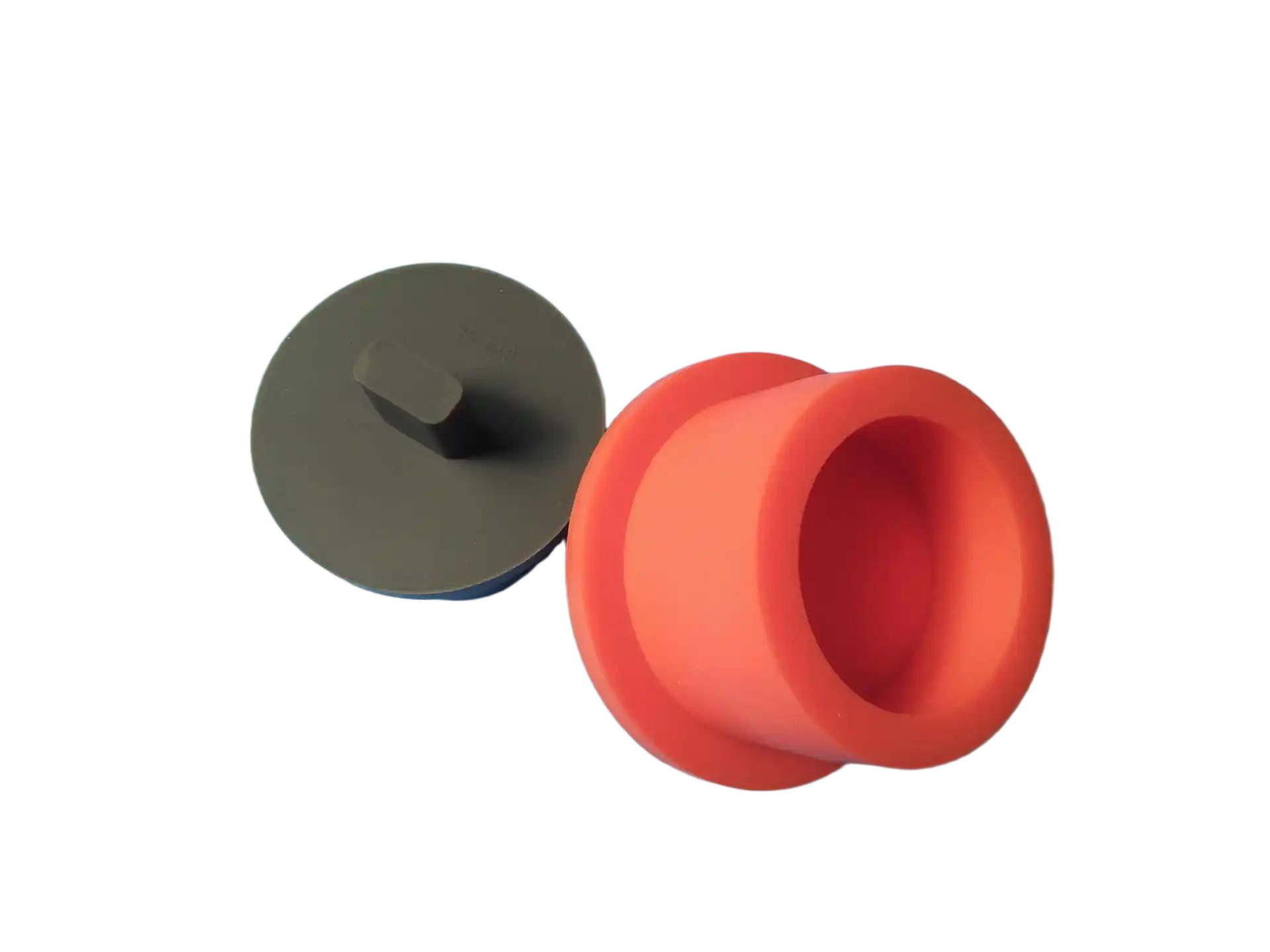
UV aging also affects gaskets, seals, and plastic components: a gasket that is not UV-stable can crack and leak after a few seasons, and the replacement cost in the field is far higher than the material difference. The seal and plastic materials should be rated for the service life.
Thermal management in sealed enclosures
Inverter enclosures are sealed against weather, which conflicts with the electronics’ need to shed heat. The thermal path must conduct heat out through the enclosure wall: a metal enclosure with a thermal interface to the power stage, internal heatsinks, or a convection path that does not break the seal. Vents allow airflow but admit dust and moisture, so outdoor enclosures rely on conduction and radiation rather than open airflow, and the thermal design must be validated at the sun-heated ambient temperature, not at the lab bench. The enclosure’s color and finish affect solar absorption, and the thermal budget should include the sun load on the box. A sealed enclosure that runs hot in the field derates the electronics or shortens their life, and the fix is a thermal design that the sealed construction supports.
Thermal cycling is the second environmental load: the enclosure and its seals expand and contract daily, and the seal and the fasteners must survive the cycles without loosening or leaking. The design should be tested over the thermal cycle range, not at a single temperature.
Sealing, cable entries, and service access
An outdoor enclosure is only as good as its sealing system: the lid gasket, the cable entries, and the service access. Cable entries are the most common leak point — a wire passing through the wall needs a gland or a sealed entry that maintains the ingress rating, and multiple cables need a layout that keeps the seal intact. The lid gasket must be compressed evenly by the fastener pattern, and the enclosure should provide service access without breaking the seal every time it is opened. The service plan matters: a sealed enclosure that must be opened for maintenance needs a gasket that survives repeated opening, and the design should make the service access a controlled operation rather than a seal-breaking event.
Pressure changes also stress sealed enclosures: a box sealed in the heat of the day can draw in moisture as it cools at night unless it breathes through a filter or a vent that maintains the rating. The enclosure design should address the pressure and condensation behavior, not just the static seal.
Tolerances for tracker and mounting assemblies
Tracker and mount assemblies carry mechanical tolerances that the environment makes harder to hold. Tracker arms and brackets need tolerances that keep the mechanism aligned as it moves, and the joints must survive wear, corrosion, and thermal movement without binding. Mounting brackets and rails need tolerances that let the panels align and the clamps grip, and the field assembly should not depend on precision that the weather destroys. The design should separate the structural tolerances from the fit tolerances, mark the features that carry the mechanism, and plan the finish so the moving and bolted surfaces keep their function. The inspection should verify the datum features that the field assembly relies on, because a tracker that binds or a mount that cannot align fails in the field even when the parts measure well individually.
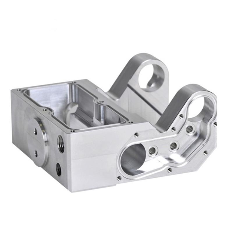
The CNC machining and sheet metal services on this site cover the component manufacturing; the solar application notes above are what turn the parts into hardware that survives the field. When the environment, the thermal budget, and the mechanical tolerances are on the drawing, the parts are specified for the solar life, not for the bench.
Specifying solar hardware from the site conditions
A site example shows how the environment writes the specification. Two installations of the same inverter enclosure are planned: one in a dry inland climate and one on a coastal roof where salt air and sun dominate. The inland unit uses a standard powder-coated enclosure with a convection path; the coastal unit specifies a corrosion-resistant coating system, UV-stable gaskets, and a sealed thermal path, because the salt air attacks the finish and the sun degrades the seals. The electronics are the same; the enclosures differ because the site conditions differ. The specification should be written from the site: the temperature range, the sun load, the salt or chemical exposure, the ingress requirement, and the service access. A manufacturer that quotes the enclosure without the site data is quoting a guess, and the guess is exposed in the first coastal season.
The same logic applies to trackers and mounts. A tracker in a dusty inland site needs seals and bearing protection against dust; a tracker on a coastal site needs corrosion-resistant materials and hardware; a mount on a high-wind site needs the structural analysis and the fastener plan to match. The mechanical design should be reviewed against the site’s wind, temperature, and corrosion loads, and the manufacturing specification should carry the environment with the drawing. When the site conditions are on the drawing, the parts are quoted, coated, and tested for the place they will live — and the solar system performs for the decades it is designed to serve.
Field lessons should be written back into the drawing. When a coastal installation shows finish failure at a specific joint, the lesson belongs in the specification: the coating class at that joint, the isolation hardware, or the gasket material is updated, and the revised drawing becomes the standard for the next site. The same applies to thermal lessons — an enclosure that derates in a hot site drives a thermal design change — and to mechanical lessons from tracker wear. A solar hardware program that records the field failures and updates the manufacturing specification is a program that improves with every installation; one that treats each site as a one-off repeats the same fixes. The specification should carry a revision history tied to the field lessons, so the next site quote starts from the accumulated experience rather than from the original assumptions.
The cost of getting the environment wrong is not the part; it is the field service call, the downtime, and the reputation of the system. A coating that fails in year three, a seal that leaks in year five, or a tracker that binds after a season costs far more than the difference between the right and wrong material at the drawing stage. The specification that invests in the environment up front — the coating test, the UV-stable seal, the corrosion-resistant hardware — is the specification that avoids the service cost later. Solar hardware is bought for decades, and the manufacturing decisions should be made with the decades in view rather than the first season. The buyer who asks the supplier “what will this look like after ten years” is asking the question that the specification should answer.
If you are sourcing custom hardware for a solar system and want the enclosure, corrosion, and tolerance plan reviewed for the field environment, the 6CProto team can work from your site conditions to the manufacturing specification.