

Vacuum and Cleanroom Parts Answer to the Environment
Vacuum and cleanroom hardware answers to the environment before it answers to the drawing. The material must not outgas into the chamber, the surfaces must not shed particles into the process, and the cleaning must be verified, not assumed. Machining these parts is as much about the material state and the surface condition as about the geometry.
The environment is defined by numbers: the vacuum level the part must survive, the temperature range, the chemical exposure, and the cleanliness class of the process it serves. A chamber component rated for high vacuum has different material and surface requirements than a fixture in a class 100 cleanroom, and both differ from a part that contacts aggressive chemicals. The RFQ should state these numbers, because they drive the material, the surface, and the cleaning. A part specified as “for cleanroom use” without a class leaves the supplier to guess the standard.
The environment also sets the failure modes to design against. In vacuum, the failure mode is outgassing and virtual leaks, trapped volumes that release gas slowly; in a cleanroom, it is particle generation and contamination; in chemicals, it is attack and residue. Design against the specific failure mode: no trapped pockets where gas or liquid collects, surfaces that can be cleaned, and materials that survive the exposure.
Materials and Outgassing Behavior
Outgassing is a rate, not a property you can guess. Every material releases absorbed water, volatiles, and process residues at a rate that depends on the material, the surface area, the temperature, and the pump-down history, which is why the same polymer grade can behave differently in two chambers. The design-side controls are to minimize surface area where possible, avoid materials known to release volatiles, and specify the surface condition that shortens the pump-down, because a rough machined surface with absorbed machining residue outgasses longer than a cleaned, dried surface. The measurement that matters is the part’s behavior under the actual vacuum and temperature, which is why the material data is a starting point and the part’s test is the evidence.
Virtual leaks deserve the same attention as outgassing because they are a design feature, not a material problem. Threaded blind holes, overlapping joints, and trapped pockets hold a volume of gas that bleeds into the chamber slowly after pump-down, which looks like a leak and wastes schedule. The drawing should break trapped volumes where possible, vent the pockets, and cross-drill where the design allows, and the machining should confirm that the features are actually open. A design reviewed against the virtual-leak failure mode costs nothing at the CAD stage and saves a long troubleshooting session at the chamber.
Material choice is an outgassing decision. PEEK combines strength, chemical resistance, and low outgassing, which makes it a default for wafer-handling and chamber components; PEI offers similar properties with different cost and processing trade-offs; and metals such as aluminum, stainless, and titanium appear where strength, grounding, or stiffness dominates. The material data, outgassing rates, water absorption, and chemical compatibility, is the starting point, and the part’s test is the evidence. State the environment and confirm the material against it rather than assuming a material is cleanroom-safe because it is a common engineering plastic.
Machining changes the material’s surface state. A machined surface has more area than a molded one, and the tool marks, residues, and micro-burrs can trap contaminants or release them slowly. The machining process for these parts should use sharp tools and appropriate coolant, followed by cleaning that removes the residue. The surface finish requirement is therefore part of the environment spec: the machined surface is specified not only for geometry but for its cleanliness-relevant properties.
Particle and Burr Control in Machining
Material selection for these parts is a shortlist, not an open menu. Aluminum 6061 appears in chamber furniture and fixtures where weight, cost, and passivation by anodizing matter; stainless 316L shows up in chambers and ultra-high-vacuum components where low outgassing and corrosion resistance dominate; titanium serves high-temperature or chemically aggressive spots; and the polymers PEEK and PEI cover insulating, non-magnetic, and wafer-contact roles. Each choice trades outgassing, strength, weight, and cleanability, and the grade and surface treatment belong on the drawing in the same way the geometry does.
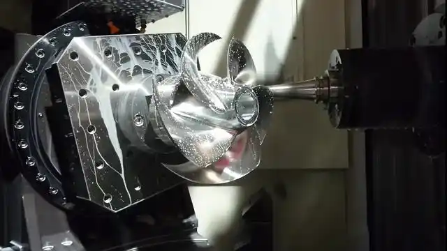
Cleanliness starts at the machine. Burrs and chips that remain on the part become particles in the process, and a trapped chip in a pocket is a contamination event waiting to happen. Particle control starts with the machining parameters: a sharp tool with the right parameters produces cleaner edges than a worn tool that smears and tears the material, and the tool path matters for the burr direction and the chip behavior.
After machining, the part is deburred, by hand, with brushes, or by methods that reach the internal features, and the result is checked. For features that trap chips, such as blind pockets and cross-holes, the design should consider how the feature will be cleaned and verified, because a feature that cannot be cleaned is a contamination risk regardless of the machining quality. Handling is part of particle control: a clean part that is touched with bare hands, set on a dirty surface, or packed in a dusty box is contaminated before it ships. The handling and packaging requirements belong in the RFQ: gloves, clean packaging, and protection of the critical surfaces.
Cleaning and Verification Steps
Cleaning is a process step, and verification is what makes it real. Agree the cleaning and verification steps with the supplier: what the part is cleaned with, how the cleanliness is checked, and how it is handled afterward. The verified part is the part that enters the environment clean.
Cleaning methods follow the material and the contaminant. Aqueous cleaning with the right chemistry suits many metals and polymers; ultrasonic cleaning reaches internal features; solvent cleaning serves specific residues. The method must not damage the material or leave its own residue. Specify the cleanliness target and the method class, and let the supplier select the process that meets it. Verification can be a visual inspection, a particle count, a rinse test, or a surface analysis, depending on the requirement, and the method and acceptance are agreed before the order with the record accompanying the part.
Measurement Capability for Tight Features
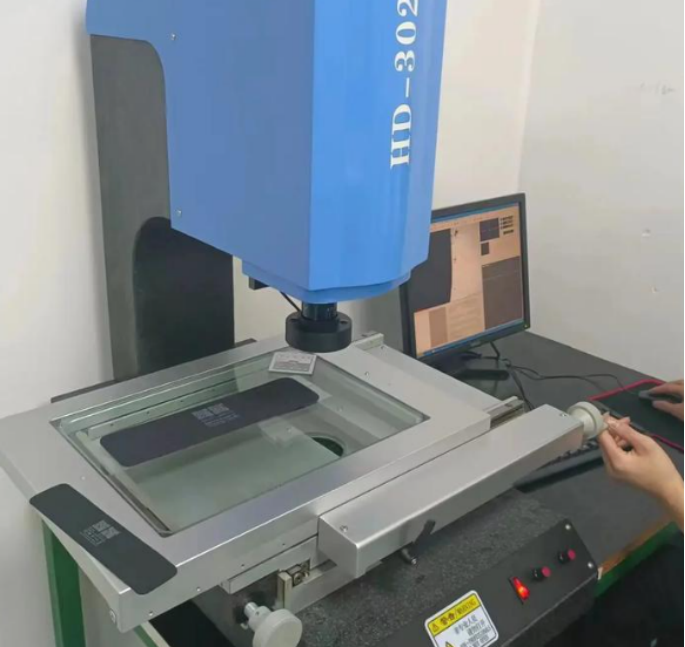
Cleanroom parts carry tight features, and the measurement must be capable of verifying them. A micron-level position or a critical bore needs a measurement method with the resolution to match, and the inspection plan is part of the process. Measurement in a cleanroom context also has an environmental component: the part is measured in a controlled, temperature-stable, clean environment so the reading reflects the part’s true state rather than the room’s. The inspection plan should state the measurement environment and the temperature control.
The packaging and transport step is often the weakest link. Even a perfectly cleaned part is re-contaminated by a finger, a polyethylene bag with the wrong slip, or a foam insert that sheds. Agree the packaging class, the glove discipline, and the final protection of critical surfaces, and verify the arrival condition as part of the delivery acceptance rather than assuming the clean state survived the box.
Documentation for Audited Environments
Audited environments run on documentation. The RFQ should define which records are required: material certificates, inspection records, process records for cleaning and handling, and the traceability chain for the material lot. The documentation accompanies the part, with the delivery, whether in the system or in the shipment, and the supplier should confirm the documentation scope before quoting. The documentation that supports an audit is the documentation that was planned, not assembled afterward.
The CNC machining service and the precision machining service cover the tolerance levels these parts require, and the micro machining article explains how critical features are managed from prototype to production. The CMM inspection framework covers the dimensional evidence side.
Conclusion
Vacuum and cleanroom hardware is environment-defined: materials that do not outgas, surfaces that do not shed, cleaning that is verified, and documentation that is planned. Request a cleanroom-part process review with the environment, the material, and the documentation requirements, and the engineering team can confirm the machining and cleaning plan. The NIST cleanroom and measurement references provide the class definitions and measurement language the acceptance criteria use.
Project Input Checklist
Environment: vacuum, chemical, temperature, cleanliness level. Material selection and outgassing behavior. Edge and particle-control requirements. Cleaning and verification steps. Measurement method for the tight features. Documentation scope in the RFQ.
FAQs
Why do vacuum parts need specific materials?
Because the material must not outgas volatiles into the chamber or absorb contaminants that later release. PEEK, PEI, and selected metals behave predictably in these environments.
How is particle control handled in machining?
Through edge condition, absence of trapped chips, and cleaning as part of the process. The cleanliness requirement is specified and verified, not assumed.
How is cleanliness verified?
With agreed cleaning and verification steps: what the part is cleaned with, how the cleanliness is checked, and how it is handled afterward. The verified part is the part that enters the environment clean.