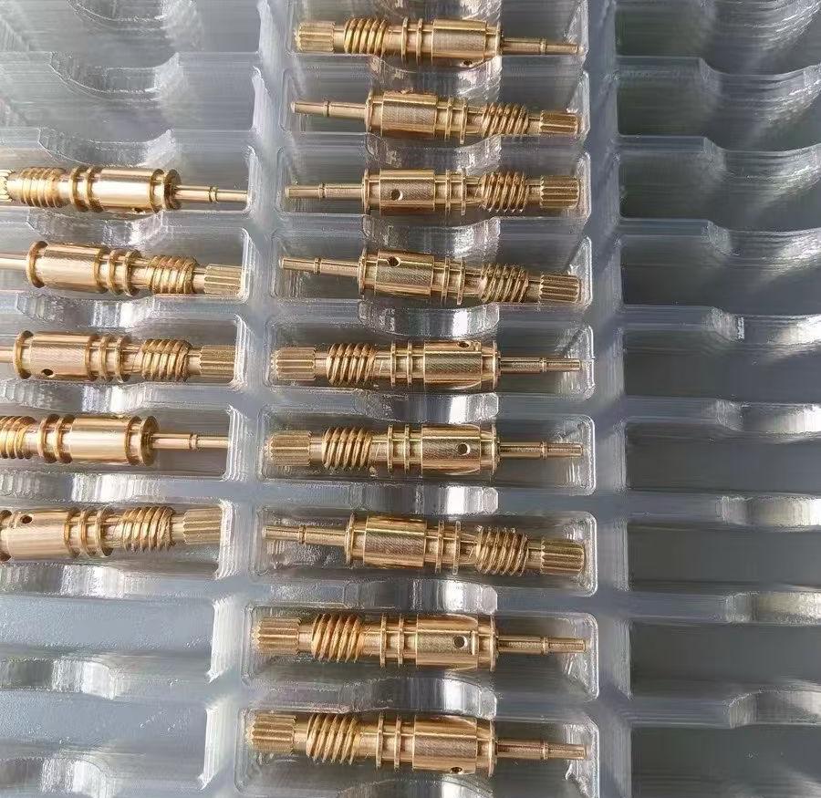
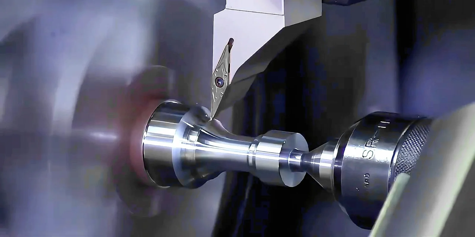
Brass and copper turning are CNC lathe processes that produce precise cylindrical components from these non-ferrous alloys. Brass offers superior machinability, faster cycle times, and lower cost, making it ideal for high-volume fittings and connectors. Copper excels in electrical and thermal conductivity, suited for bus bars and heat exchangers. Selection depends on application requirements, balancing performance, manufacturability, and budget.

How Do Brass and Copper Differ in Machining Performance?

Brass machines significantly faster than copper due to its alloy composition, with free-cutting grades like C360 achieving machinability ratings near 100% compared to copper’s 20-40%. This results in shorter cycle times, reduced tool wear, and better surface finishes for brass. Copper requires slower speeds, sharper tools, and more careful chip control to prevent built-up edge and tearing.

The fundamental difference lies in material structure. Brass, an alloy of copper and zinc (often with lead for free-cutting variants), produces short, brittle chips that break cleanly during turning. This chip behavior allows higher feed rates and cutting speeds without compromising surface quality. Copper, particularly electrolytic tough pitch (ETP) grades like C110, generates long, stringy chips that can wrap around tools and workpieces, necessitating chip breakers, lower parameters, and frequent tool inspection.

Property C360 Free-Cutting Brass C110 ETP Copper
Machinability Rating 100% (baseline) 20-40%
Electrical Conductivity ~26% IACS 101% IACS
Thermal Conductivity ~115 W/m·K ~391 W/m·K
Tensile Strength 340-470 MPa 220-345 MPa
Typical Cycle Time Fast, high feeds 3-5× longer
Relative Part Cost Baseline 2-3× higher

For production environments, brass dominates volume manufacturing of connectors, terminals, and mechanical hardware where its moderate conductivity suffices. Copper remains essential for high-current bus bars, RF components, and heat sinks where maximum conductivity is non-negotiable. Engineers should evaluate whether the 4× conductivity advantage of copper justifies the 2-3× cost premium and extended lead times for their specific application.

What Are the Primary Applications for Turned Brass and Copper Parts?

Turned brass components dominate plumbing fittings, valves, electrical connectors, and decorative hardware due to their corrosion resistance, machinability, and aesthetic appeal. Copper turning serves electrical bus bars, heat exchangers, RF cavities, and thermal management systems where superior conductivity is critical. Both materials find use in automotive, aerospace, marine, and consumer electronics sectors.

Brass turning applications leverage its combination of properties:

  • Plumbing and fluid systems: Valves, fittings, and faucet components benefit from brass’s corrosion resistance in water and its ability to hold tight tolerances for leak-free seals.

  • Electrical hardware: Connectors, terminals, and switch components use brass for its adequate conductivity, spring properties, and resistance to fretting corrosion.

  • Marine hardware: Propeller shafts, bushings, and fittings exploit naval brass alloys (C464) with added tin for enhanced seawater corrosion resistance.

  • Musical instruments: Bell sections, valves, and mouthpieces require brass’s acoustic properties and ability to achieve mirror finishes.

  • Consumer goods: Door handles, clock components, and decorative trim capitalize on brass’s gold-like appearance and tarnish resistance.

Copper turning applications prioritize conductivity:

  • Power distribution: Bus bars, contact fingers, and high-current terminals demand copper’s 101% IACS conductivity to minimize resistive losses.

  • Thermal management: Heat sink bases, cold plates, and thermal interface components use copper’s 391 W/m·K thermal conductivity for efficient heat transfer.

  • RF and microwave systems: Waveguide components and cavity resonators require copper’s low surface resistance at high frequencies.

  • Welding electrodes: Resistance welding tips leverage copper’s thermal conductivity to dissipate heat while maintaining structural integrity.

In rapid prototyping contexts, 6CProto supports both materials for projects ranging from functional prototypes to production runs. Their CNC turning capabilities handle the full spectrum from simple bushings to complex multi-feature components, with DFM analysis helping teams optimize designs before committing to tooling.

Which Brass and Copper Alloys Are Best Suited for Turning Operations?

Free-cutting brass C360 leads turning applications with its optimized lead content for chip breaking and surface finish. For copper, ETP C110 dominates general machining while tellurium copper C145 offers improved machinability for demanding applications. Alloy selection balances machinability, conductivity, strength, and corrosion resistance requirements.

Brass alloy selection depends on application priorities:

C360 (Free-Cutting Brass): Contains 61.5% copper, 35.5% zinc, and 3% lead. This is the industry standard for turned parts, offering the best machinability rating of 100%. Ideal for high-volume production of fittings, fasteners, and connectors where moderate conductivity suffices.

C260 (Cartridge Brass): 70% copper, 30% zinc composition provides excellent cold workability and corrosion resistance. Used for ammunition casings, decorative trim, and plumbing fittings requiring forming after machining.

C464 (Naval Brass): 60% copper, 39% zinc, 1% tin delivers superior seawater corrosion resistance. Standard for marine hardware, propeller shafts, and chemical processing equipment.

C280 (Muntz Metal): 60% copper, 40% zinc offers high strength for architectural trim and industrial fittings requiring structural performance.

Copper alloy options:

C110 (ETP Copper): Electrolytic tough pitch copper with 99.9% purity delivers maximum conductivity. The default choice for electrical and thermal applications despite challenging machinability.

C145 (Tellurium Copper): Additions of 0.4-0.7% tellurium improve machinability to ratings around 85% while retaining 90%+ of copper’s conductivity. Preferred for high-volume electrical components requiring both performance and manufacturability.

C101 (OFE Copper): Oxygen-free electronic grade for ultra-high conductivity applications like RF cavities and vacuum systems, though machinability remains challenging.

When selecting alloys, engineers should request material certifications from suppliers like 6CProto, who can provide ISO 9001:2015 certified materials with traceability. For projects requiring both conductivity and reasonable machinability, tellurium copper C145 often represents the optimal compromise, though at higher material cost than C110.

Why Does Chip Control Matter More in Copper Than Brass Turning?

Copper’s long, stringy chips create tool wrapping, surface tearing, and safety hazards if not properly managed, whereas brass produces short, brittle chips that evacuate cleanly. Effective chip control in copper requires chip breakers, lower parameters, and optimized tool geometries to prevent built-up edge and workpiece damage.

Chip formation mechanisms differ fundamentally between these materials. Brass, particularly leaded grades like C360, exhibits discontinuous chip formation where the material fractures at the shear plane, creating small segments that fall away from the cutting zone. This behavior allows aggressive cutting parameters without chip-related complications.

Copper’s high ductility and strain-hardening tendency produce continuous chips that maintain structural integrity as they flow along the tool face. These chips can:

  • Wrap around rotating workpieces, causing sudden tool breakage or workpiece ejection

  • Built up on cutting edges, creating false tool geometry and poor surface finishes

  • Tangle in chip conveyors or coolant systems, requiring frequent operator intervention

  • Create safety hazards when ejected at high velocity in long, sharp strands

Practical chip control strategies for copper turning:

  1. Use chip breakers: Insert geometries with aggressive chip breaker grooves force chip curling and fracture at predictable intervals.

  2. Optimize cutting parameters: Reduce feed rates to 0.1-0.2 mm/rev and cutting speeds to 150-250 m/min for C110, significantly lower than brass’s 300-500 m/min capability.

  3. Select appropriate tool materials: Carbide inserts with polished faces and sharp edges (0-5° rake) minimize built-up edge. Avoid high-speed steel for production work.

  4. Apply high-pressure coolant: Direct coolant at 70-100 bar through the insert breaks chips and prevents work hardening. Brass often machines well dry, but copper benefits from aggressive cooling.

  5. Use positive rake angles: 10-15° positive rake reduces cutting forces and encourages chip flow away from the workpiece.

Experienced machinists sometimes employ unconventional techniques like reverse spindle rotation with inverted tooling for manual copper turning, though this requires careful setup and is not standard practice in CNC production environments.

How Do Surface Finish Requirements Influence Material Selection?

Surface finish requirements often dictate material choice, with brass achieving Ra 0.4-0.8 μm routinely while copper struggles to reach Ra 0.8-1.6 μm without secondary operations. Applications requiring electroplating, sealing surfaces, or optical finishes typically favor brass unless conductivity demands copper.

Brass’s superior machinability translates directly to better as-machined surface quality. The short-chip, low-friction cutting action produces consistent finishes suitable for:

  • Sealing surfaces: Valve seats and O-ring grooves in brass achieve the smoothness needed for leak-tight performance without grinding or honing.

  • Electroplating substrates: Brass’s smooth surface accepts zinc, nickel, chrome, and silver plating with minimal preparation, reducing finishing costs.

  • Cosmetic components: Decorative hardware and visible parts benefit from brass’s ability to achieve near-mirror finishes directly from turning.

Copper presents surface finish challenges:

  • Built-up edge: Copper’s tendency to adhere to tool faces creates torn surfaces and inconsistent roughness, particularly at higher speeds.

  • Material tearing: Ductile copper can smear rather than cut cleanly, leaving feed marks and micro-tears that require post-machining removal.

  • Work hardening: Surface layers can harden during cutting, creating uneven finishes and complicating subsequent operations.

For applications where both conductivity and surface finish are critical, consider these approaches:

  1. Tellurium copper C145: Improved machinability yields better finishes than C110 while retaining 90%+ conductivity.

  2. Two-stage machining: Rough machine copper, then finish with light cuts (0.1-0.2 mm depth) using sharp, polished inserts to achieve acceptable Ra values.

  3. Secondary operations: Plan for grinding, polishing, or lapping in process routing when copper surface requirements exceed as-machined capability.

  4. Alternative materials: Evaluate whether brass with 26% IACS conductivity suffices, avoiding copper’s surface finish penalties entirely.

Suppliers offering CMM inspection and DFM analysis can help identify surface finish risks early. 6CProto’s engineering team, for instance, reviews critical surface requirements during quoting to recommend appropriate alloys and machining strategies, preventing costly rework after parts are produced.

What Are the Critical Design Constraints for Brass and Copper Turned Parts?

Design constraints center on wall thickness, feature aspect ratios, and tolerance selection, with copper requiring more conservative limits than brass due to its lower strength and higher cutting forces. Minimum wall thicknesses of 1-1.5 mm for brass and 1.5-2 mm for copper prevent deflection and chatter during turning.

Key design considerations for turned brass and copper components:

Wall thickness: Thin walls deflect under cutting forces, causing dimensional errors and poor surface finishes. Brass’s higher tensile strength (340-470 MPa) allows thinner walls than copper (220-345 MPa). For high-volume production, maintain walls above 1 mm for brass and 1.5 mm for copper; prototype work can push to 0.75 mm brass with careful fixturing.

Feature aspect ratios: Deep, narrow features like small-diameter holes or slots create tool deflection and chip evacuation problems. Limit hole depth-to-diameter ratios to 10:1 for brass and 6:1 for copper without specialized tooling. Consider gun drilling or EDM for deeper features.

Tolerance selection: Brass holds ±0.025 mm routinely on turned diameters; copper may require ±0.05 mm or looser without secondary operations. Tighter tolerances on copper demand slower speeds, multiple passes, and temperature control, increasing costs significantly.

Undercuts and internal features: Internal bores and undercuts require boring bars with limited rigidity. Brass allows deeper reaches with smaller tools; copper needs larger, stiffer tools or shorter reaches. Design external access where possible to avoid internal machining.

Thread considerations: External threads machine well in both materials, but internal threads in copper risk tap breakage from chip accumulation. Use thread milling for internal copper threads in production, or design for self-tapping screws in lower-volume applications.

Chamfers and deburring: Copper’s ductility creates burrs that resist removal. Design generous chamfers (0.3-0.5 mm) at part edges to facilitate deburring. Brass chips break cleanly, leaving minimal burrs.

DFM analysis during design review identifies these constraints before tooling commitment. 6CProto offers DFM services that flag problematic features, suggest geometry modifications, and recommend material alternatives that maintain function while improving manufacturability. Early engagement with manufacturing expertise prevents costly redesigns after prototype validation.

When Should You Choose Rapid Prototyping Over Production Turning Methods?

Rapid prototyping suits design validation, low-volume functional testing, and iterative development where flexibility and speed outweigh per-part cost. Production turning becomes economical at volumes above 50-100 parts, where cycle time optimization and dedicated tooling reduce unit costs despite higher initial setup.

Decision factors for prototyping versus production:

Volume thresholds: Below 50 parts, rapid prototyping’s minimal setup and standard tooling typically cost less than production tooling amortization. Between 50-500 parts, evaluate based on complexity and tolerance requirements. Above 500 parts, production turning almost always wins on unit cost.

Design maturity: Unproven designs benefit from rapid prototyping’s flexibility to accommodate design changes between iterations. Once designs stabilize, production tooling locks in geometry for consistent, cost-effective manufacturing.

Lead time requirements: Rapid prototyping services like 6CProto can ship qualifying projects in as little as 24 hours, ideal for urgent design reviews or trade show samples. Production turning requires 2-4 weeks typical for tooling and first articles, though per-part costs drop significantly.

Tolerance and finish needs: Prototype parts often accept looser tolerances (±0.1 mm) and standard finishes to accelerate delivery. Production tooling achieves tighter tolerances (±0.025 mm) and optimized finishes through dedicated tool geometries and process parameters.

Material considerations: Both phases support brass and copper, but production runs benefit from material optimization—selecting specific heat treatments, grain structures, or alloy variants that improve performance or machinability. Prototyping typically uses standard stock sizes and grades.

Testing requirements: Functional prototypes validate fit, form, and basic function. Production parts undergo full qualification testing including dimensional inspection, material certification, and performance validation. CMM inspection becomes standard in production to ensure conformance.

For projects transitioning from prototype to production, maintain design continuity by using the same supplier for both phases. 6CProto’s range from prototyping to production support enables seamless scaling, with DFM insights from prototype work informing production tooling decisions.

What Quality Validation Steps Are Essential for Brass and Copper Turned Components?

Essential validation includes dimensional inspection via CMM, material certification verification, surface finish measurement, and functional testing for critical applications. Statistical process control during production ensures consistency, while first-article inspection confirms tooling and process capability before full-volume runs.

Comprehensive quality validation protocol:

First-article inspection (FAI): Complete dimensional validation of initial production parts against all drawing requirements. Document results with CMM reports showing actual measurements, not just pass/fail status. Verify critical features including diameters, lengths, concentricity, and runout meet specifications.

Material certification: Require mill certificates showing alloy composition, mechanical properties, and traceability to heat/lot numbers. For brass, verify lead content in C360 falls within 2.5-3.7% for optimal machinability. For copper, confirm conductivity ratings match requirements (101% IACS for C110, 90%+ for C145).

Surface finish validation: Measure Ra values on critical surfaces using profilometers. Brass should achieve Ra 0.4-0.8 μm as-machined; copper may require Ra 0.8-1.6 μm. Document measurements on inspection reports for traceability.

Dimensional process capability: For production runs, calculate Cp and Cpk values on critical dimensions. Target Cpk ≥ 1.33 indicates process capability with adequate margin. Monitor trends to detect tool wear or machine drift before parts exceed tolerance.

Functional testing: For sealing applications, pressure test samples to verify leak-tight performance. For electrical components, measure contact resistance and current-carrying capacity. For rotating components, balance and runout testing ensures smooth operation.

Visual inspection: Examine all parts for surface defects including tool marks, chatter, burrs, and material tears. Copper parts require particular scrutiny for built-up edge artifacts and smeared surfaces.

Corrosion testing: For marine or chemical applications, conduct salt spray testing (ASTM B117) to verify corrosion resistance meets requirements. Naval brass C464 should exceed 500 hours without red rust; copper should show only uniform patina formation.

ISO 9001:2015 certified suppliers like 6CProto maintain documented quality systems ensuring consistent validation across projects. CMM inspection capabilities enable precise dimensional verification, while material traceability provides confidence in alloy selection and performance characteristics.

6CProto Expert Views

6CProto engineering perspective: When evaluating brass versus copper for turned components, prioritize application requirements over material familiarity. For high-volume electrical connectors, brass C360 often provides adequate conductivity at one-third the cost and cycle time of copper. Reserve copper C110 for applications where every percentage point of conductivity matters—high-current bus bars, RF cavities, or thermal interfaces where 4× higher conductivity justifies the manufacturing premium. Always request DFM analysis before finalizing designs; features that machine easily in brass