

Updated
The useful distinction is the purpose and acceptance of the build. A development sample should answer a defined question; a production part should meet its released requirements repeatedly. Choosing the route means matching geometry, material, quantity and evidence to that purpose, then planning how the design will move to its next stage.
Understand what each term describes
Custom manufacturing describes the relationship between the part and its specification. Instead of selecting an unchanged catalog item, the buyer provides or approves a design, material and acceptance requirements. Production may involve machining, molding, fabrication, casting or additive manufacturing. Quantity can range from one part to a recurring production order.
Rapid prototyping describes a development workflow focused on learning through physical iterations. “Rapid” is relative to the design cycle, and the process can include CNC machining as well as 3D printing. A prototype may test appearance, packaging, assembly, mechanical behavior or a production process. Its value depends on whether it can answer that particular question.
The Formlabs rapid prototyping application overview distinguishes visual and functional uses of printed prototypes. That distinction is useful beyond printing: a convincing appearance model is not automatically valid for load, chemical or thermal testing. Record the intended use so nobody mistakes a convenient sample for proof of requirements it was never built to reproduce.
Choose the process by the question and final requirements
Use geometry and required material behavior to narrow the process, then consider revision risk and quantity. Compare the complete route, including tooling, secondary operations, finishing and inspection. Generic tolerance or lead-time ranges can conceal the characteristics that make a particular order difficult.
| Route | Useful development or production role | Main trade-off to evaluate |
|---|---|---|
| CNC machining | Functional metal or plastic parts with accessible features | Stock form, tool access, setup and material removal |
| 3D printing | Complex geometry, fast shape changes or suitable end-use designs | Material behavior, orientation, supports and post-processing |
| Injection molding | Process-representative polymer parts and repeat quantities | Tooling commitment, draft, gates and shrinkage |
| Sheet metal | Brackets and enclosures based on formed sheet | Bend access, joining, springback and dimensional relationships |
| Casting or soft-tool replication | Repeated shapes where the selected material and route fit | Master accuracy, tool life and property differences |
Use rapid prototyping services to discuss development options and CNC machining when stock material and machined interfaces are central to the test. A process name does not prove that a particular feature is feasible.
For example, an electronics enclosure may be printed first to check packaging, then machined to evaluate a metal heat path, and finally molded if the released product is polymer. Each build answers a different question. Keeping the exterior shape similar does not make their thermal or structural results interchangeable.
Write a test-purpose statement before ordering a prototype
Name the decision the build must support, the response to measure and the conditions under which the result will be used. A useful statement might be: confirm connector access with the intended cable and assembly tools. Another might be: compare two mounting layouts under a defined vibration fixture. These lead to different prototype requirements.
Mark the features that must match the intended design and those that may be simplified. Connector spacing may be essential for packaging while surface color is optional. A structural test may require the intended grade, thickness and mounting stiffness while permitting a simplified nonloaded cover. This gives the manufacturer room to reduce effort without weakening the experiment.
Agree on the acceptance or decision rule before testing. If the build is only for design review, document that limitation. If it supports a quantitative comparison, define the measurement, repeat conditions and relevant uncertainty. A test that produces data without a decision rule can consume a prototype budget while leaving the original design question unanswered.
Match material and process fidelity to the evidence needed
A prototype material can be acceptable when its differences do not influence the question. Printed resin may be suitable for a hand-access model, but it cannot automatically establish the impact behavior of an injection-molded thermoplastic. Machining a plastic housing can reproduce some dimensions while missing molding-dependent features such as weld lines and fiber orientation.
For additive parts, orientation, build conditions and post-processing can affect properties. The NIST characterization of additive manufacturing materials project addresses material characterization challenges. Treat process and material identity as part of the evidence rather than assuming a shared polymer or alloy name establishes equivalent behavior.
Keep a short fidelity record for each build: intended production material, actual prototype material, manufacturing route, relevant differences and permitted use of the results. When the next stage changes process, identify which tests need repeating. This makes substitution a controlled engineering choice and prevents an early success from being carried forward as unsupported production evidence.
Use DFM to resolve process-specific constraints
Design for manufacturing review asks whether the intended route can produce the part consistently and economically while preserving function. It is not a generic request to relax every tolerance. Good feedback identifies the feature, the manufacturing constraint and an alternative that leaves the design intent intact.
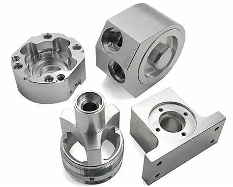
For machining, review tool access, internal radii, deep features, workholding and datum transfer. For molding, examine wall transitions, draft, parting lines, gates, ejection and shrinkage. For sheet metal, review bend access, reliefs, joining and the references used after forming. A prototype made by another process can hide these constraints.
Make changes before committing to costly tooling where possible, but do not accept every DFM suggestion automatically. The design owner should assess the functional impact and approve the revised definition. Record exceptions that remain in the design and how the supplier plans to control them. Early review is useful only when it leads to specific decisions and an updated, consistent release package.
Distinguish rapid tooling from direct prototype fabrication
Rapid tooling makes a mold, die, pattern or other tool used to produce subsequent parts. Direct prototyping makes the part itself. These approaches can be combined, but their cost, schedule and validation questions differ. A quickly produced tool may help evaluate a production material without having the life or process stability of the intended production tool.
The Formlabs rapid tooling overview explains this tool-versus-part distinction. If a development mold is proposed, define the required quantity, material, operating conditions and acceptable tool degradation. Do not assume that making several successful parts demonstrates the mold is ready for an extended production campaign.
When considering injection molding, clarify tooling ownership, cavity count, expected life, maintenance, storage and modification terms in the quotation. Identify which aspects of the development tool represent production and which differ. The purpose may be to evaluate fit or material behavior, not to establish cycle time or process capability for a later multi-cavity tool.
Prepare a revision-controlled RFQ and acceptance package
Provide the model, drawing, revision, material condition, quantity, finish and intended use. State critical dimensions and relationships, cosmetic requirements and documentation. If a model-based definition is the authority, establish how annotations and tolerances are conveyed and which files belong to the released data set.
The ASME Y14.41 standard addresses preparation and revision of digital product definition data. A 3D shape exported without its manufacturing information can leave the supplier guessing about acceptance. Resolve conflicts between the model, drawing and quote assumptions before authorizing manufacture.
For a prototype, state which requirements are intentionally relaxed and why. For a production-intent order, define the report, certificates and inspection condition needed for release. Ask the supplier to list proposed substitutions or deviations in writing. Keep that agreement attached to the revision so a successful sample does not become a vague precedent for every future build.
Compare the total development cost, not only unit price
An early prototype is economical when it reduces uncertainty that would otherwise cause expensive rework. Include engineering effort, setup, tooling, finishing, inspection, shipping and the expected number of revisions in the comparison. A low unit price can be misleading if the route requires a costly tool that will change after the first test.
For repeat parts, a simple planning model is total cost = fixed preparation cost + quantity × variable part cost + downstream costs. If two routes have comparable outputs, their nominal break-even quantity can be calculated from the difference in fixed costs divided by the difference in variable costs. This is only useful when both routes meet the same acceptance requirements.
Include the cost of changes and failed learning. A visually accurate material substitute may be cheap but unsuitable for the test, requiring another build. A slower prototype route may avoid a false decision. Ask quotations to identify assumptions, excluded operations and revision charges so procurement can compare complete alternatives rather than incomplete price lines.
Move to production through explicit release gates
Transition when the design, material and process evidence are sufficient for the intended production duty. Typical gates include functional design approval, process-specific DFM resolution, controlled files, representative pilot parts and an agreed inspection plan. The required evidence depends on risk, application and customer requirements; a calendar milestone alone does not qualify the part.
The NIST additive manufacturing part qualification project highlights qualification challenges for AM components. More generally, geometry alone is not enough when properties, internal defects or surface condition determine performance. Identify which evidence applies to the actual production route and which came from a different prototype configuration.
Run the pilot under the proposed production conditions where practical. Resolve deviations before scaling, and define change control for material, tooling, finishing and inspection. The goal is a released process capable of repeating the required result. A single passing prototype is a useful milestone, but it is not the same evidence as repeatable production.
Select a partner using project-specific evidence
Evaluate whether the supplier can review the design, explain the proposed route, identify limitations and provide the required records. Ask for confirmation against the actual geometry and material, not only examples of unrelated parts. Clarify who is responsible for secondary finishing and inspection and how exceptions will be communicated.
For orders that progress beyond development, establish material identification, lot records, revision control and notification of relevant process changes. Review low-volume manufacturing as a possible bridge where demand or design stability does not justify a larger commitment. A bridge order should still have clear acceptance rather than inheriting informal prototype permissions.
Use the first delivery to evaluate both the part and the agreement: did the report cover the requested features, were substitutions disclosed, and did the final condition match the quote? Close these gaps before the next order. A useful manufacturing relationship preserves design intent through changing quantities and revisions, with enough evidence to know what each delivered part represents.
Describe the next decision your parts need to support, then send 6CProto the model, drawing and RFQ. Include prototype or production intent, material, quantity and acceptance evidence so the review can compare suitable manufacturing routes.
FAQ
Is rapid prototyping always 3D printing?
No. CNC machining, fabrication, casting and molding can support rapid development when they fit the question and schedule. The term describes the learning workflow; the process is selected for the required geometry and evidence.
Can a prototype be used as an end-use part?
Only if it meets the released requirements for that use. Its original label is less important than material, process, inspection and qualification evidence. A prototype built with approved relaxations should not automatically enter service.
When should I invest in production tooling?
After the relevant design questions and process constraints are resolved enough to justify the commitment. Compare demand, revision risk, tooling terms and required qualification. A fixed order quantity alone does not establish readiness.