

An IoT gateway prototype works on the bench and dies in the field: the enclosure traps the processor heat, the plastic lid attenuates the antenna, and the outdoor unit fills with condensation through an unsealed cable entry. IoT hardware fails at the intersection of enclosure, thermal, antenna, and power — and each of those is a manufacturing decision that the software team cannot see. Edge devices are physical products first: they need an enclosure that protects the electronics, a thermal path that keeps the processor alive, and an antenna window that lets the radio work. Designing those together with the manufacturing process is what turns a demo into a deployable product.
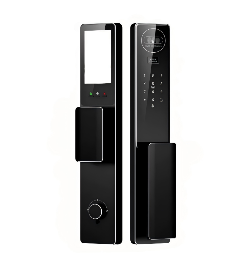
The IoT bill of materials: enclosure, thermal, antenna, and battery
An edge device is more than a board in a box. The enclosure must protect the electronics from the environment, the thermal design must move heat away from the processor, the antenna needs a window or a ground plane that does not kill the signal, and the power path — battery or mains — needs its own space and thermal behavior. Each element interacts: a metal enclosure solves thermal and shielding but blocks an internal antenna; a plastic enclosure passes the radio but traps heat and may need shielding for EMC. The bill of materials should be designed as a system, with the enclosure, thermal, and antenna decisions made together rather than sequentially.
Enclosure materials and finishes for indoor and outdoor devices
The environment sets the enclosure: indoor devices can use molded plastic or sheet metal with cosmetic finishes, while outdoor devices need UV-resistant materials, sealing, and corrosion protection. Aluminum enclosures conduct heat and provide shielding, but they need antenna windows or external antennas and a finish that survives the environment; plastic enclosures are light and radio-transparent but need thermal management and, often, internal shielding. The material choice should be made with the thermal and radio requirements in hand, because changing the enclosure material later changes every other design decision.
The finish matters as much as the material: an outdoor aluminum enclosure needs a durable coating, a consumer device needs a cosmetic class with an acceptance sample, and any device that will be cleaned needs a finish that survives the cleaning agent. The consumer-electronics and enclosure capability on this site covers the manufacturing side of that choice.
Thermal paths: heatsinks, vents, and potting
Edge processors generate heat, and the enclosure decides where it goes. A metal enclosure can act as a heatsink with a thermal interface to the processor; a plastic enclosure needs internal heatsinks, vents, or a metal plate. Vents allow airflow but let in dust and water, so outdoor devices usually rely on conduction through the enclosure rather than convection. Potting fills the electronics with a thermally conductive or protective compound, which helps both heat and moisture but makes rework nearly impossible. The thermal design should be validated at the operating ambient temperature, not at the bench, because the enclosure that is cool indoors can cook in a sunlit cabinet outdoors.
| Thermal route | Best for | Trade-off |
|---|---|---|
| Metal enclosure as heatsink | Outdoor and higher-power devices | Needs antenna window or external antenna |
| Internal heatsink + vents | Indoor devices with airflow | Vents affect dust and ingress rating |
| Potting | Sealed, harsh-environment modules | No rework; thermal path must be designed in |
The table is the thermal decision map; the enclosure, the antenna, and the service plan all follow from it.
Antenna-friendly design: windows, plastics, and grounding
Radio performance depends on the antenna environment. A metal enclosure can act as a shield and detune an internal antenna; a plastic window in the metal can restore the link if it is positioned and sized for the antenna. The ground plane, the antenna placement, and the nearby components all affect the radiated performance, so the mechanical design should reserve the antenna zone and keep conductive parts out of it. Designers who treat the antenna as a black box discover the range problem at certification, where the fix is a redesign. Reserve the antenna space early, prototype the radio in the actual enclosure, and measure the real link budget rather than assuming the datasheet range.
For plastic enclosures, the plastic itself can load the antenna, and the effect varies with the material and the wall thickness. Test the radio with the production material, not with a hand-held board, because the enclosure is part of the antenna system.
Prototype-to-low-volume path for edge hardware
Edge devices typically start as machined or 3D-printed enclosures for bench testing, then move to sheet metal, urethane casting, or injection molding as the quantity and the design mature. The prototype should validate the thermal and radio behavior in the real geometry, because those do not scale with the process — a machined aluminum box and a molded one behave differently. At low volume, machined or sheet-metal enclosures with CNC-machined features are practical; at higher volume, molding or casting changes the design rules for draft, walls, and inserts. The manufacturing route should be chosen with the volume forecast, because the enclosure design that is optimal for ten units is rarely optimal for ten thousand.
Plan the assembly and service path at the same time: how the board is installed, whether the device is potted or serviceable, and how the antenna and cable entries are handled. The rapid prototyping and low-volume services cover the route from machined prototype to pilot production, and the transition is smoother when the enclosure design anticipates it.
A gateway example shows the system design in practice. An outdoor IoT gateway with a cellular radio, a 20 W processor load, and a sealed enclosure is being developed. The team starts with a plastic enclosure for cost, then discovers that the processor needs a metal thermal path and the cellular antenna needs clearance from the metal. The design resolves the conflict by using an aluminum body as the heatsink, adding a plastic antenna window in the lid over the reserved antenna zone, and potting the sealed cable entry. The prototype is machined from aluminum with the window cut out, the radio is measured through the window with the production antenna, and the thermal test runs at the rated ambient temperature with the enclosure closed. The results drive two changes before tooling: the window is repositioned for the antenna, and the thermal interface material is changed. At low volume, the machined enclosure with a molded window insert serves the pilot; at higher volume, the same geometry transfers to a die-cast or sheet-metal construction with the window molded in. The product ships because the enclosure, thermal, and antenna decisions were made as one system and validated in the real geometry — not because the radio happened to work on the bench. That is the manufacturing discipline IoT hardware needs: every enclosure decision is also a thermal, radio, and service decision.
Before enclosure tooling starts, confirm the operating environment, the processor’s thermal budget at ambient, the antenna location and its window, the ingress sealing plan, and the volume that selects the manufacturing route. Prototype the radio and the thermal path in the real geometry, and measure the link budget and the case temperature at the rated conditions. The review that answers these points is the one that ships a device that works where it is installed.
Frequently asked questions
Should an IoT enclosure be metal or plastic?
The answer follows the thermal, radio, and environmental requirements, not a preference. Metal conducts heat and provides shielding but blocks internal antennas; plastic is radio-transparent but needs a thermal path and may need shielding. Define the power, the environment, and the antenna location first, and the enclosure material decision becomes a system trade rather than a guess.
How do you seal an outdoor IoT enclosure?
With a designed sealing system: a gasket or seal at the lid, sealed or potted cable entries, and a drainage or breathing plan for pressure changes. The ingress rating is earned by the joint design and verified by testing, not by a rubber strip alone. Confirm the cable entry method and the gasket material with the enclosure supplier before tooling.
Can an internal antenna work in a metal enclosure?
Rarely, without a window or a modified enclosure. Metal around the antenna acts as a shield and detunes the radio. Options include a dielectric window, an external antenna, or a metal-free zone designed into the enclosure. Prototype and measure the actual link before committing to the design, because antenna behavior is geometry-specific.
The deployable device in one paragraph
IoT hardware succeeds when the enclosure, thermal path, antenna, and power are designed as one system with the manufacturing route in view. Choose the material by environment and radio behavior, validate the thermal and RF performance in the real geometry, and plan the prototype-to-low-volume path before the design is locked. The devices that deploy without field failures are the ones whose physical design was tested in the conditions where they will live.
If you are developing an IoT edge device and want the enclosure, thermal, and antenna design reviewed against a manufacturing route, the 6CProto team can work from your board and environmental requirements to the prototype and pilot build.