

What Makes Up an Industrial Robot System
Industrial robot parts should be manufactured according to their function, load path, accuracy requirement, material behavior, and expected production volume. CNC machining suits rigid, precise components; injection molding supports repeatable plastic parts at scale; 3D printing accelerates iteration; and sheet metal works well for guards and enclosures. The best route balances performance, validation risk, cost, and design stability.
An industrial robot system includes structural components, motion components, end-of-arm tooling, protective parts, electrical enclosures, sensors, cables, and control hardware. From a manufacturing perspective, it helps to separate parts by the consequence of their failure:
- Structural parts. Arm links, bases, mounting plates, frames, brackets, and joint housings carry static and dynamic loads.
- Motion-related parts. Shafts, couplings, gearbox interfaces, bearing seats, pulleys, and actuator mounts need alignment and surface condition over cosmetics.
- End-of-arm tooling. Gripper fingers, vacuum tooling, welding fixtures, camera mounts, and adapters change frequently during automation development.
- Protective components. Covers, cable-management parts, guards, doors, and enclosures protect people, wiring, and sensors.
- Electrical and sensing components. Controller housings, sensor brackets, and connector panels manage heat and routing.
A standard collaborative robot may need a custom aluminum adapter plate to carry a camera, a pneumatic gripper, and cable routing hardware. The plate looks simple, but its stiffness, hole pattern, and center-of-gravity effect can change the robot’s performance, which is why even a small interface deserves a real engineering review.
Matching the Process to Each Component
- CNC machining. Arm links, housings, shafts, fixtures, and gripper bases; precision and broad material choice, with material-removal cost becoming visible on large or deeply pocketed parts.
- Injection molding. Covers, cable guides, housings, grips, and repeatable plastic components; consistent at volume with integrated features, but requires tooling and a stable design.
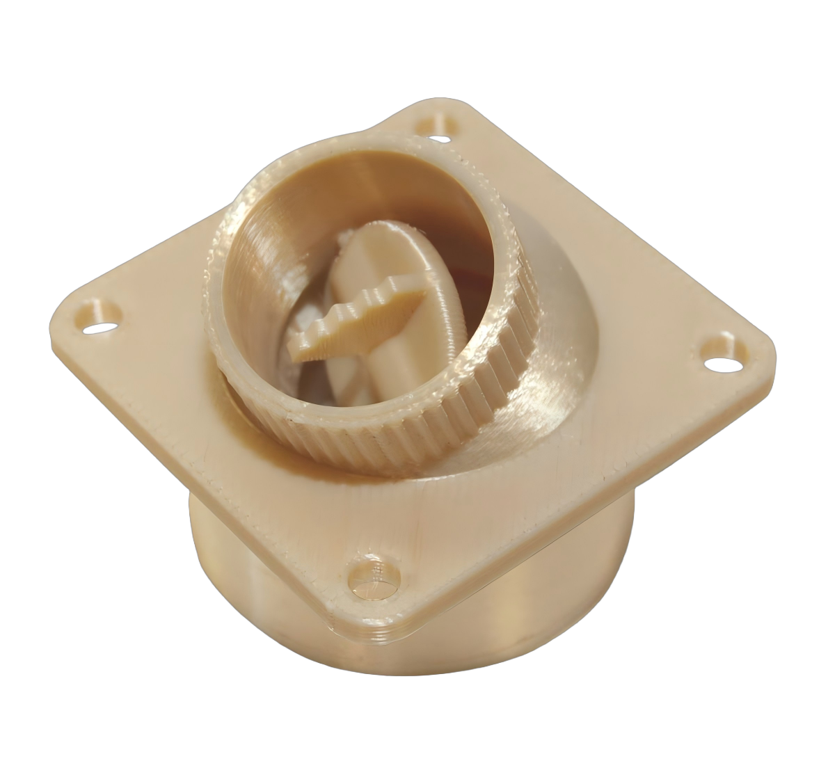
- 3D printing. Gripper fingers, jigs, ducting, ergonomic covers, and test housings; fast iteration and complex geometry with no dedicated tooling, but printed properties and finish may not match final needs.
- Sheet metal fabrication. Guards, electrical cabinets, panels, brackets, and machine frames; efficient for enclosures and weldments, with bend radii, fasteners, and flat-pattern rules shaping the design.
The process should follow the component’s critical features rather than its overall appearance. A robot cover with a highly visible exterior may be molded, while the hidden mounting inserts, precision adapter, and sensor bracket may be machined. Combining processes is often more practical than forcing an entire assembly into one route.
Loads and Tolerances Shape the Design
Robot parts experience repeated motion rather than a single static load. A lightweight arm bracket can appear adequate under a stationary payload yet flex during rapid direction changes, and that deflection can reduce positioning accuracy, disturb a camera calibration, or shorten bearing life. Define loads from the actual operating condition: payload, acceleration, stopping forces, vibration, cable forces, impact events, duty cycle, and thermal change.
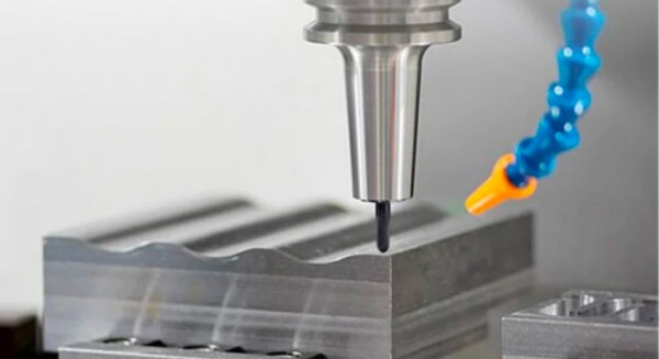
Assign tight tolerances only where function requires them, at the bearings, dowel locations, mating faces, and sensor reference surfaces that decide the robot’s accuracy. An excessively tight tolerance on every feature adds manufacturing and inspection cost without improving performance. The result guidelines mirror the machining logic described in the CNC machining tolerance guide: features are toleranced by their role in the assembly, not by habit.
Material Selection Goes Beyond Strength
A stronger material is not automatically a better robot material. For moving components, stiffness-to-weight ratio often matters more than maximum strength; for protective covers, impact resistance and chemical compatibility matter more than rigidity. Aluminum alloys appear in lightweight links, fixtures, and housings because they machine efficiently and reduce moving mass. Steel is appropriate for high-load bases, wear components, threaded interfaces subject to repeated service, and welded frames. Stainless steel suits washdown, food, medical, and corrosive environments, though it adds cost and mass.
Engineering plastics appear in covers, cable guides, and end-effectors that carry low loads. Their performance must be assessed in the actual environment: a plastic part near heat, UV exposure, lubricants, cleaning chemicals, or repetitive clamp loads behaves differently than it does on the bench. Material selection also covers joining: a thin plastic wall may not hold a repeatedly serviced screw without an insert, and a dissimilar-metal joint needs attention to corrosion, coating, and thermal expansion. Those are design decisions, not default supplier choices.
Prototypes Engineered to Answer Questions
Prototypes reduce risk only when they answer defined questions: does the gripper reach the part, does the cable path interfere with motion, does a bracket vibrate, and can technicians assemble and service the tool? An effective sequence is: early models verify envelope, reach, collisions, ergonomics, and cable routing; functional prototypes test loads, fastening, sensor placement, pneumatic routing, and repeatable assembly; pilot parts verify the intended production material and process; and production-validation parts confirm that repeated parts meet the release requirements.
A 3D-printed gripper finger can quickly verify grip geometry and clearance, but it may not validate high-cycle fatigue, abrasive wear, or long-term dimensional stability; a machined or molded version may be needed before release. The iteration speed argument for printing is strongest when the design is still changing, as it frequently is for end-of-arm tooling. When that happens, 6CProto’s staged combination of rapid prototyping and production processes lets each build answer its own question without blocking the next one.
DFM Risks Specific to Robot Components
For CNC-machined parts, the risks sit in internal corners, deep narrow pockets, small threaded holes, thin webs, and multi-setup features. Inside corners cannot be perfectly sharp with a rotating tool, so mating parts need reliefs, and deep cavities force long tools that reduce rigidity and may harm surface finish or cost. For molded parts, review wall-thickness transitions, draft, ribs, bosses, undercuts, gate location, parting lines, and shrinkage-sensitive dimensions; a cover with deep vertical walls and no draft may need redesign before tooling. For sheet metal, check bend radius, flange clearance, hole-to-bend spacing, fastener access, weld distortion, and whether the part can be formed in a repeatable sequence; a multi-panel enclosure is often easier to fabricate and service than a one-piece shell.
A DFM review is most valuable before hard tooling or a production release. The review should return specific feedback on geometry risks, inspection practicality, material availability, and process constraints, not just a price. Buyers should define which results they need on which dimensions, because CMM inspection is most useful where positional relationships and complex surfaces are critical.
Quality Validation Before Installation
Quality validation should involve the design engineer, manufacturing engineer, quality personnel, buyer, and the technicians who install and maintain the robot. Define acceptance criteria before manufacturing: critical dimensions and their inspection method, material and surface treatment, thread or insert requirements, assembly checks with gauges or functional fixtures, and the documentation required for the application. A CMM is valuable for complex machined geometry and positional relationships, but it is not a substitute for a clear drawing and inspection plan.
When to Commit to Production Tooling
Move to production tooling when the geometry, material, environment, assembly method, and demand are stable enough to justify the commitment. Tooling too early locks in a poor design; waiting too long raises piece cost and exposes the program to inconsistent supply. For a molded protective cover, tooling makes sense after fit around motors, connectors, cable paths, and safety clearance is verified; for a custom end-effector in a changing process, machining or additive routes may stay appropriate longer, because revisions are likely.
Before authorizing tooling, confirm the design has passed functional testing in representative conditions, an assembly and serviceability review, a material and finish evaluation, a DFM review with the chosen process, inspection planning, and a realistic demand and spares strategy. Robot cells run for years while tooling and electronics change, so maintain controlled CAD, drawings, inspection criteria, material definitions, and revision history to avoid ordering a visually similar but incompatible replacement part.
Choosing a Supplier for Robot Work
Evaluate suppliers on process fit, quality communication, revision control, and realistic delivery assumptions. The vocabulary for that evaluation, and for the drawings that support it, follows conventions maintained by standards bodies such as NIST measurement and standards guidance. Ask the supplier to review the actual model and drawing, not a category label. The response should name assumptions, manufacturing concerns, material questions, and features that affect cost or schedule, and state the method for checking critical features, material traceability, and handling of engineering changes. For tight schedules, ask what conditions govern expedited shipping rather than treating a fast promise as a standard guarantee. When a robot system spans several processes, a partner that covers machining, printing, molding, and sheet metal in one quality system, such as 6CProto’s sheet metal route for guards and cabinets alongside its other services, reduces the coordination overhead of the build.
Frequently Asked Questions
Can 3D-printed robot parts be used in production?
Yes, but suitability depends on the material, load, temperature, wear exposure, safety role, quantity, and required consistency. Printed parts are often practical for custom grippers, cable guides, jigs, and low-load covers, but they should be validated before use in critical or high-cycle applications.
How should buyers specify tolerances for robot components?
Specify tight tolerances only for features that affect assembly, motion, location, sealing, or measurement. Identify functional datums, mating parts, and inspection requirements, and avoid applying tight tolerances to surfaces that do not carry the thing.
When is injection molding better than CNC machining for robot parts?
Injection molding is usually better for stable plastic parts needed repeatedly, such as covers, cable guides, and ergonomic interfaces. CNC machining is more flexible for prototypes, revisions, precision metal parts, and lower volumes.