

Rapid sheet metal prototyping turns a CAD model into physical metal parts in days by using laser cutting, CNC bending, and modular fixtures instead of dedicated stamping dies. The purpose is not to make the cheapest part, but to validate fit, stiffness, heat behavior, and assembly with production-grade metal before committing to hard tooling. That distinction—learning speed over unit cost—drives every process, material, and design decision in this article. When lead time and iteration frequency matter more than piece price, sheet metal prototyping usually wins; when the question is precision in solid material or complex organic shapes, CNC machining or 3D printing become the alternatives.
How a Rapid Prototype Is Actually Built
The workflow starts from the 3D CAD model and moves through five stages: a design-for-manufacturing (DFM) review, flat-pattern generation with bend allowances, cutting, forming, and assembly.
- DFM review: the manufacturer checks bend radii, flanges, and hole locations against standard tooling before any metal is cut. This is the cheapest place to find a flange that cannot be formed or a slot placed too close to a bend line.
- Flat-pattern generation: the 3D geometry is unfolded into 2D blanks with bend allowance applied, so the formed part lands at the intended dimension instead of shrinking or growing at each fold.
- Cutting: a fiber laser cuts the profiles, holes, and reliefs. Laser cutting needs no dedicated tooling and absorbs design changes in minutes, which is why it is the workhorse of rapid work even when the endgame is stamping.
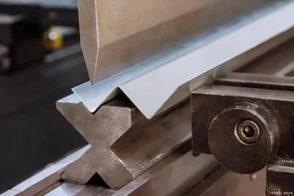
- Forming: a CNC press brake bends the flanges and hems, using programmable angles and radii instead of custom dies.
- Assembly: spot or TIG welding, riveting, and hardware insertion join the parts, with welding sequences chosen so they are easy to adjust after the first trial batch. Fasteners and PEM hardware belong here too, since they test the threaded interfaces that real assembly will use.
A disciplined shop runs a handful of parts first, bends them, and immediately checks key dimensions and angles. Observations such as springback at a flange or interference at a corner feed back into an updated flat pattern before the rest of the prototype lot is cut. In a typical rapid project, that loop delivers functional parts in a few days for simple geometry and one to two weeks for complex assemblies with finishing and hardware.
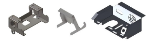
Processes That Work without Hard Tooling
Prototype sheet metal leans on a small set of universal processes, each with a clear role:
- Fiber laser cutting: the default for most profiles in thin-to-medium stock. Fast, precise, and easy to change between revisions.
- Waterjet cutting: the answer for thick plate or heat-sensitive materials, since a cold cut leaves no heat-affected zone.
- CNC punching: worthwhile when a design carries many repeated holes or knock-outs, because it is faster on patterns and migrates toward production stamping.
- Press braking: all bends and hems, with programmable angles and radii on universal tooling.
- Spot and TIG welding: assembly joints that behave close to production welds, plus hardware insertion for threaded features and PCB mounting.
The only tooling a prototype run typically needs is flexible fixturing—clamping plates, magnet-based supports, or simple angle jigs—that a shop reuses across projects. Hard dies get no money locked in while the design can still change. If repeated-hole patterns and knock-outs dominate the part, CNC punching earns its place as a bridge toward stamping; otherwise laser cutting plus CNC bending covers most enclosures and brackets.
Why Prototypes Should Match Production Material
Sheet metal prototyping earns its value from realism, and realism comes from material. Common choices are CR4 mild steel, 5052 or 6061 aluminum, and 304 stainless steel, with thicknesses from about 0.5 mm for light covers up to 3–4 mm for structural brackets. These grades bend predictably, coat well, and are stocked in common gauges so cutting can start within hours of approval.
Material switching is the trap. A part prototyped in mild steel does not behave like stainless: springback, stiffness, and sometimes corrosion performance change materially. If the production material changes after prototyping, plan one additional prototype pass in the final material rather than trusting the earlier results. The same logic applies to thickness—a thinner gauge could meet layout needs while changing stiffness enough to fail the application.
Validating Assembly, Cooling, and EMC on the Prototype
The value of a sheet metal prototype is that it answers the questions a rendering cannot. Assembly validation confirms that panels, brackets, and hardware align in reality; cooling validation checks airflow paths and heat paths on real metal, where thermal behavior differs from plastic prints; electromagnetic validation, where the product needs it, depends on the same enclosure continuity and seams that production will have. These are the validations that most often rename a prototype revision, because they combine the material, the geometry, and the assembly in one artifact.
That is also why the prototype should include the interfaces it will meet: a bracket tested without its mating panel, or a door checked without its seal, answers only part of the question. Include the fasteners, the gaskets, and the neighboring parts in the build, and record the small realities—oil-canning, weld pull, hardware interference—that the flat model cannot show. Those observations are the raw material for a Rev B that is closer to production by design, not by chance.
Design Rules That Keep Prototypes Fast
Designing for sheet metal prototyping is not the same as designing for 3D printing or machining, and getting it wrong is the main source of slow rounds. The rules that keep a part fast to cut and form:
- Use realistic bend radii matched to material and thickness; radii that are too tight crack the bend or need special tooling.
- Keep holes away from bend lines; a hole that intersects a bend either distorts or forces a second operation.
- Add generous corner reliefs so flanges do not tear where they meet.
- Use consistent bend directions to reduce setups, and avoid tiny features that laser cutting or forming cannot hold.
- Call out only critical dimensions with tight tolerances; a part that demands ±0.05 mm on an outer cosmetic edge spends inspection time it does not need.
These rules matter for another reason: the prototype is also the first draft of production. Bend radii that work with standard press-brake tooling, joints weldable by robot or rivetable in fixtures, and recorded shop-floor tweaks all carry directly into the production plan. A prototype does not de-risk manufacturing unless it uses the geometry, material, and processes that production will use.
Prototyping Tolerances without Dedicated Tooling
It is worth being explicit about tolerance expectations, because prototype sheet metal quotes often assume the wrong band. Without hard tooling, laser-cut profiles and single-plane hole patterns hold tight, repeatable geometry because each feature is referenced to the same machine setup. Formed relationships are different: every bend adds springback and thickness effects, so a dimension that crosses two or three flanges carries noticeably more variation than one on a flat surface. The useful approach is to put prototype-critical dimensions on the drawing, agree the bands with the supplier up front, and keep cosmetic edges under a general note. When the design later moves to tooling, the critical bands carry over and the general note can be retained.
Material gauges deserve the same honesty. A 2 mm bracket and a 1.2 mm cover behave differently under the same bend tooling, and a prototype built in the wrong thickness validates the wrong geometry. Prototype in the production gauge, with the production bend radius, and record the actual measured angle against the nominal callout on each revision.
When Do Prototypes Become Tooling?
There is no fixed volume at which prototypes become stamping, but three signals mark the transition: the design stops changing, order sizes become predictable, and prototype cost starts approaching the amortized cost of tooled production. A practical approach is a pilot stage—a few hundred units built with refined prototype processes—to capture real cost and quality data before investing in progressive dies or automated welding fixtures. The trigger is financial, not technical: invest in hard tooling when the expected run makes it cheaper than continuing to prototype, and not before.
Rapid sheet metal prototyping works because it separates what needs to be true from what can wait. Fit, stiffness, heat behavior, and assembly are validated in real metal within days; die investment waits until the design and volumes justify it. For a deeper comparison of the trade-offs against subtractive and additive routes, see our guide on choosing between 3D printing and CNC machining. Team that match material to production, apply bend rules from the first CAD file, and plan the tooling handoff early get the fastest path from concept to a part that can be produced.
Frequently Asked Questions about Rapid Sheet Metal Prototyping
Do I need detailed 2D drawings, or is 3D CAD enough?
3D CAD is enough to start flat patterns, but a drawing is what carries material, finish, critical dimensions, and assembly notes. Combining both yields the fewest surprises: CAD for geometry, the drawing for requirements.
How close to production tolerances are prototype parts?
Laser-cut and bent prototypes usually hold production-like tolerances on critical features—single-plane geometry is especially repeatable. Without dedicated tooling, variability is higher across multiple bends, so comparison against the shop’s stated bands matters more than chasing numbers on non-critical edges.
What if the part will eventually be stamped?
Prototype it in laser-cut sheet metal anyway. The flat pattern, bend sequence, and assembly method transfer directly to progressive dies, and the prototype run reveals the geometry issues that would otherwise surface as expensive die changes. Formal references on sheet metal forming practice and material behavior are maintained by standards organizations such as ASTM, whose standards catalogue covers metalworking and materials testing standards.