

Optical-quality CNC milling of acrylic (PMMA) depends on three things: choosing cast PMMA, running stable high-speed, low-chip-load toolpaths with sharp diamond or polished carbide cutters, and tightly controlling heat and vibration. When the surface turns frosty, controlled flame or vapor polishing, followed by clean-room-level handling, restores glass-like transparency suitable for lenses and light pipes.
Last updated:
What makes CNC-machined acrylic turn cloudy instead of clear?
Cloudiness in CNC-machined acrylic comes from micro-fractures, smeared plastic, and thermal stress created when feeds, speeds, and chip evacuation are not optimized. Cast PMMA usually machines clearer than extruded grades because it has lower internal stress and better optical homogeneity, which is why I always specify cast sheet or blocks for optical parts at 6CProto.
When I review failed customer parts, the frosted look nearly always maps to three issues: dull tools, wrong flute geometry, and recutting of chips. A sharp 1–2 flute plastic end mill, running fast enough to cut but not melt, produces long, glossy chips that carry heat away instead of welding back to the surface. Chip recutting creates a milky band that no amount of simple buffing will fully remove.
Another subtle cause is using down-cut tools “borrowed” from wood setups. They trap hot chips in the kerf and iron them into the wall, giving a satin, non-uniform haze that is especially visible in light pipes. I recommend an upcut or neutral helix with aggressive air blast so the chips have no chance to stay in the cut. On deep pockets, a programmed retract-and-blow step between passes can make the difference between hazy and almost-transparent walls.
Internal stress is the third culprit. If you climb-mill too aggressively, especially in thin webs or delicate lens features, the part springs during machining and relaxes afterward, creating stress birefringence and subtle distortion. For high-end optical PMMA, 6CProto will combine stress-relieved cast stock with gentle finish passes and, for critical parts, a low-temperature anneal before final polishing.
Why is cast PMMA preferred for optical CNC milling?
Cast PMMA offers better clarity, less internal stress, and more consistent refractive properties than extruded acrylic, which makes it the standard for lenses, light pipes, and display windows. In practice, I’ve seen that the same toolpath yields visibly clearer surfaces on cast stock, with fewer stress cracks at sharp corners and better performance after vapor polishing.
How should feeds, speeds, and depth of cut be tuned for clear acrylic?
For optical acrylic, run high spindle speed, modest feed, and shallow stepdowns so the cutter slices cleanly without generating excess heat. Think in terms of surface speed and chip load: you want continuous chips, no dust, and a surface that looks almost polished right off the machine. If chips start to melt, lower RPM or increase feed until they break cleanly.
On the shop floor, I do not rely on generic “plastic” presets. Instead, I start with manufacturer data and then tune by watching chip shape and listening to the cut. For a 6 mm single-flute PMMA cutter, running 18,000–22,000 rpm with a 0.04–0.08 mm chip load per tooth is often a good starting window, but we tighten or loosen this based on tool stick-out, rigidity, and geometry. The goal is a “dry” sound and cool chips you can touch.
Depth of cut is another lever. For roughing blocks of PMMA, we may run 0.5–1.0 times tool diameter axially if the workholding is very rigid. For optical surfaces, final finishing passes drop to 0.05–0.2 mm with small stepover and constant-load strategies to avoid chatter marks. When customers push for speed on light pipes, I explain that shaving a few minutes off cycle time can cost hours in re-polishing if the finish banding becomes visible once illuminated.
At 6CProto, we also use trochoidal or adaptive toolpaths for deep pockets in acrylic. These reduce sudden load changes and heat spikes, so the walls remain clearer before polishing. Combining this with high-pressure air blast and, when appropriate, a light mist helps keep the temperature in a safe band without fogging the surface.
Which cutting parameter combinations typically yield the best pre-polish finish?
The most reliable combination is a high spindle speed, low radial stepover, shallow axial depth, and stable climb-milling strategy, paired with a very sharp, polished-flute tool. When you see continuous, ribbon-like chips and an almost glossy wall before any polishing, you know the feeds and speeds are in the right window for optical work.
How do tool selection and diamond cutting impact optical surface quality?
Diamond tools, especially PCD or MCD-tipped cutters, dramatically improve edge gloss and reduce micro-chipping on PMMA, giving you a surface that sometimes needs only light vapor polishing. Compared with standard carbide, diamond’s extreme hardness and sharpness maintain a crisp edge much longer, which is critical on long light-pipe runs or large lenses where tool wear bands would otherwise show.
In my experience, the biggest mistake is assuming any “sharp” carbide will do for optics. A plastic-specific, polished carbide tool is adequate for many prototypes, but if you’re chasing uniform transmission in a 300 mm light guide, you quickly see every tool wear transition as a brightness step. Switching to diamond cutters at 6CProto has turned some previously “un-polishable” designs into production-ready components.
Tool geometry is equally important. I prefer single-flute or two-flute designs with generous chip gullets for PMMA, along with a small rake angle that slices rather than ploughs. For contouring lenses, ball-nose diamond tools with tight runout control produce scallops that are much easier to remove during polishing. On delicate micro-features, such as Fresnel prisms, I’ll often specify a dedicated small-diameter diamond cutter rather than reusing a general-purpose tool.
What are the practical trade-offs of using diamond tools on PMMA?
Diamond tools cost more upfront but repay that cost through longer life, fewer tool changes, and reduced polishing effort. On multi-cavity lens or light-pipe projects, I often find that diamond milling can eliminate one or two polishing steps, which more than offsets the tooling price while delivering more consistent optical performance from part to part.
Why does chip evacuation and cooling matter so much for clear acrylic?
Efficient chip evacuation prevents recutting and smearing that cause haze and micro-scratches, while proper cooling keeps acrylic below its softening point so the surface doesn’t partially melt and reharden with a frosted look. A good PMMA process uses directed air blast or vacuum extraction to carry chips away in real time, avoiding the “snow storm” that quickly destroys clarity.
From my own runs, the visual difference between good and bad chip control is obvious even before you touch the part. With strong air or vacuum, the flute gullets stay open and the wall appears glossy. Without it, chips tumble in the toolpath, and within a few passes you see cloudy streaks, especially at entry and exit points. This effect is magnified in narrow slots and deep pockets.
I also treat coolant very cautiously with acrylic. Flood coolant can cause stress crazing if the formulation is not compatible with PMMA, and droplets can leave marks that show later under backlighting. That is why 6CProto typically prefers dry machining with air blast for PMMA, or a carefully tested minimum-quantity mist if absolutely needed. The goal is to manage heat with cutting parameters and airflow, not to rely on liquid coolant to rescue a bad cut.
How can shops verify that their chip evacuation strategy is adequate?
You can audit the process by inspecting chips and surfaces mid-run. If chips are long, solid, and expelled quickly while the cut zone remains visible, your evacuation is working. When you see powdery, fused chips in the kerf or hear chatter as chips recut, it’s time to increase air blast, optimize vacuum shoe design, or adjust toolpaths before chasing optical clarity with extra polishing.
How can post-process polishing restore frosted acrylic to optical clarity?
Post-process polishing—typically a combination of fine abrasive sanding, buffing, and vapor or flame polishing—can remove the frosted layer and reflow the surface to restore clarity. The trick is to remove just enough material to pass below the damaged zone without deforming features or introducing waviness that distorts light. For optical parts, every polishing step should be controlled and measurable.
In practice, I never let operators jump straight from a 400-grit sandpaper to a flame or vapor pass. The abrasive progression matters. We often go from 800 to 1200 to 2000 or higher, checking roughness along the way, before moving to buffing wheels and compounds. Only when the surface haze is very uniform and fine do we apply vapor or flame, which then “closes” the micro-scratches into a clear skin.
Flame polishing is fast and convenient for edges but can easily round corners and introduce stress if overdone. Vapor polishing, using appropriate solvents in a controlled chamber, is much better for complex lens surfaces and closed geometries. At 6CProto, we choose the method based on geometry, thickness, and required transmission uniformity. For example, a simple guard window might get flame-polished edges, while a precision light guide receives full vapor treatment.
Which post-polishing sequence works best for optical light pipes and lenses?
A proven sequence is: fine wet sanding with progressive grits, then buffing with plastic-specific compound, followed by controlled vapor polishing and a final clean-room wash. This layered approach removes machining damage step by step, reduces residual stress, and delivers a surface clear enough for demanding optical applications without over-softening edges or distorting features.
Light transmission through polishing stages
The table below illustrates typical light transmission trends for a 10 mm PMMA light pipe as it moves through polishing stages.
What is vapor polishing, and when is it better than flame polishing?
Vapor polishing uses solvent vapor to gently soften and reflow the outermost surface of acrylic, smoothing micro-scratches and restoring transparency without direct flame contact. It excels on complex geometries, internal channels, and optical faces where uniformity and minimal edge rounding are critical, such as light guides, lenses, and microfluidic channels with tight dimensional requirements.
From my experience, vapor polishing shines when customers complain about “striping” or “applesauce” textures on curved lens surfaces that have already been sanded and buffed. A properly tuned vapor cycle can erase those high-frequency defects while preserving the macro-geometry that the CNC tool so carefully created. Flame, in contrast, is more likely to introduce uneven gloss and over-soften sharp features.
Vapor polishing does demand process discipline: precise control of exposure time, temperature, and solvent concentration. Over-exposure can cause sagging or dimensional growth, while under-exposure leaves a patchy finish. That is why 6CProto maintains part-specific recipes based on thickness, material grade, and use case. For automotive light pipes, for example, we validate transmission and distortion after polishing to ensure the optical design still performs as modeled.
When is flame polishing still the better option?
Flame polishing is ideal for simple, accessible edges and non-critical surfaces where speed is more important than sub-micron flatness. If you need an aesthetically glossy edge on a protective cover or display window, a skilled operator with a clean flame can deliver excellent results quickly, without the overhead of a vapor chamber.
How can flame polishing be controlled to avoid warping and stress?
Flame polishing must be treated like a precision thermal process: use a neutral, well-mixed flame, move at a steady speed, and keep the torch at a consistent distance so the surface just “skins over” without bubbling. Cooling must be uniform and gentle; quenching with cold air or liquid can lock in stress and lead to cracks or crazing later.
On the shop floor, I train technicians to watch the surface sheen instead of the flame itself. The acrylic should transition from matte to glossy in a second or two, with no visible ripple or flow. If the gloss appears uneven or you see slight “orange peel,” it’s a sign the material got too hot or the torch lingered. For safety, we always practice on scrap of the same thickness before touching production parts.
Furthermore, we avoid flame polishing near tight-tolerance holes or press-fit features, because even slight thermal expansion and shrinkage can shift dimensions. At 6CProto, if a part has both cosmetic edges and critical fits, we often mask or shield the critical regions during flame polishing or polish those areas purely by mechanical means. This protects dimensional integrity while still achieving the desired optical edge quality.
Can annealing help reduce flame-polishing stress?
Yes, a low-temperature annealing cycle after flame polishing can relax internal stress and improve long-term stability, especially for thicker PMMA parts. When time and budget allow, I recommend annealing critical optical components so they resist crazing and cracking during service, particularly in applications exposed to solvents or temperature swings.
Which PMMA grades and thicknesses are best for optical CNC parts?
Cast PMMA grades designed for optical use, often marketed as “optical grade” or “lens grade,” are the best starting point for clear CNC parts. They exhibit higher purity, reduced internal stress, and more consistent refractive index. For thickness, 3–20 mm is common for light pipes and lenses, but the right choice depends on structural needs and how much polishing stock you plan to remove.
In my quoting work at 6CProto, I often nudge designers toward cast sheets or blocks from reputable brands, even if they cost slightly more than commodity acrylic. The yield in terms of clarity and polishing effort is worth it. Extruded acrylic can work for covers and non-critical optics, but it tends to show stress patterns under polarized light and is more prone to cracking around tight features.
Thickness choice is a balancing act. Thicker parts offer better stiffness and more room to polish out defects, but they magnify internal imperfections and can be harder to cool uniformly during machining. Thin parts are easier to keep stress-free but can chatter or deflect under the cutter. When customers share their optical simulation data, we can help back-calculate the necessary thickness and machining allowances so the finished, polished component still meets optical path requirements.
How should designers account for material removal during polishing?
Designers should allocate a polishing allowance—often 0.1–0.3 mm per side for demanding optics—so that final dimensions are achieved after the full sanding and vapor/flame sequence. If you design to finished size and then polish aggressively, you risk thinning critical sections or shifting focal distances, especially in precision lenses and tightly toleranced light guides.
Typical material and process choices by application
How can CNC strategy be optimized specifically for light pipes and lenses?
For light pipes and lenses, CNC strategy should ensure uniform surface roughness and minimal tool marks along the light path or optical face. Use consistent stepovers and tool engagement, avoid abrupt direction changes, and plan toolpaths so the scallop pattern follows the optical design. This reduces polishing time and helps maintain the modeled light distribution.
In day-to-day practice, that means preferring constant-stepover 3D finishing for curved lenses and spiral or helical paths for circular features, rather than zig-zag patterns that leave cross-hatched marks. On long light guides, we align the toolpath with the dominant light travel direction so any residual marks are parallel to the beam and less visible. For multi-step operations, we carefully blend transitions between different tools so they don’t create brightness steps when the part is illuminated.
At 6CProto, we frequently collaborate with optical engineers to adjust fillet radii or add small blending radii that make machining and polishing more consistent. Slightly relaxing a sharp internal corner to a small radius, for instance, can eliminate a localized hot spot in polishing where defects tend to accumulate. These design-for-manufacture tweaks often pay back with more uniform illuminance and fewer iterations.
Can simulation and measurement feedback improve CNC strategies?
Yes, using surface roughness measurements and optical tests (like light transmission and uniformity mapping) to feed back into CAM strategies is extremely powerful. By correlating specific toolpaths and parameter choices with measured optical performance, we continuously refine our “playbook” for light pipes and lenses, making each subsequent project faster and more predictable.
6CProto Expert Views
“When customers ask how we get injection-mold-level clarity from CNC-milled PMMA, I tell them it’s 40% material, 40% toolpath, and 20% polishing discipline. At 6CProto, we treat every optical acrylic job as a system: cast PMMA, diamond tools, tuned feeds and speeds, and a documented polishing recipe. That’s how we keep light pipes uniform and lenses distortion-free from prototype to pilot run.”
Why choose 6CProto for CNC acrylic and optical PMMA work?
Choosing 6CProto means you get a team that has already solved the hard problems of clear PMMA machining across aerospace, medical, and automotive applications. From a single prototype lens to full sets of light pipes, we integrate CNC milling, polishing, inspection, and DFM support under one roof, compressing development time while de-risking your optical performance.
Because we operate as a one-stop shop in Zhongshan, we can iterate fast on complex optical geometries. You can submit your CAD, receive manufacturability feedback, and get polished, optically clear samples shipped in days rather than weeks. Our CMM and optical inspection capabilities ensure that what you receive matches both your drawings and your simulation expectations, not just in geometry but in functional clarity.
6CProto’s breadth of processes—CNC milling, 5-axis machining, injection molding, 3D printing, and sheet metal fabrication—also allows us to bridge from early acrylic optics to production-ready solutions. Once a CNC-milled lens or light pipe is validated, we can help you evaluate whether to stay with machining or transition to tooling, carrying over all the learning from your prototype runs.
Are there specific project types where 6CProto adds the most value?
We add the most value on projects where optical quality and time-to-market are both critical—automotive and EV lighting concepts, medical device windows and light guides, and ruggedized industrial displays. If your team needs fast, high-clarity prototypes with factory-level process insight instead of trial-and-error polishing, 6CProto is structured to deliver exactly that.
Which PMMA, and How Much Material the Polish Will Remove
Two decisions made before any cutting set the ceiling on how clear a milled acrylic part can be. The first is the material itself: cast PMMA machines and polishes to a better optical result than extruded sheet, because the cast process leaves a more uniform molecular structure and less internal stress, which is also why cast is the default for light pipes and lenses. The second is the allowance for finishing. Polishing is material removal, not a coating, so a face that must end up at a given dimension has to be machined oversize by the depth the polishing sequence will take off — and that depth depends on whether the shop finishes by hand, by vapour, or by flame.
The two clear materials are not interchangeable either, and the shop’s comparison of polycarbonate and acrylic for machined clear parts is worth reading before the grade is fixed: the choice between them trades optical quality against impact resistance, and the finish route follows the material rather than the drawing’s preference. On a part that has to be both clear and strong, the decision is usually made by which of the two failure modes matters more in service, not by which machines more easily.
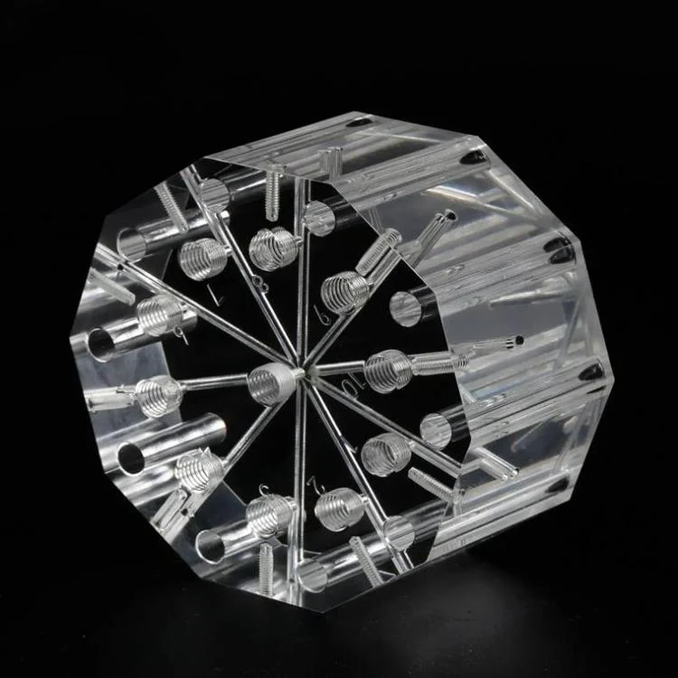
What to Specify and What to Verify
The drawing should name the material and how it was made — cast or extruded, with the grade — because the finishing route depends on it; state the optical requirement on the surfaces that carry light rather than on the whole part; and carry the oversize allowance for polishing on any face where the final dimension matters. Verification follows the same logic. Ask for the material certificate identifying the sheet type and grade, a surface roughness reading on the polished face before it is assembled, and the polishing sequence the shop used, because a part that is clear today but was flame-polished past its stress limit may craze in service. One boundary condition is worth stating plainly: clarity is a surface property, and no machining strategy recovers it after the surface has been burned, melted or left with a step that polishing has to remove at the cost of the dimensions around it.
Conclusion: How can engineers reliably achieve glass-like clarity in milled acrylic?
Engineers can achieve glass-like clarity in CNC-milled acrylic by starting with cast optical-grade PMMA, using sharp diamond or polished carbide tools with dialed-in feeds, speeds, and chip evacuation, and applying controlled, multi-step polishing. When design, machining, and finishing are treated as an integrated process—rather than isolated steps—the resulting light pipes and lenses approach molded-optical quality.
From my experience, the biggest gains come from process discipline: standardizing toolpaths for optics, documenting polishing recipes, and feeding test results back into CAM strategies. Partnering with a manufacturer like 6CProto that lives with these trade-offs every day allows you to move beyond “clear enough” and consistently hit the clarity your optical design deserves.
FAQ
Why does CNC-machined acrylic turn cloudy instead of clear?
Because the cutting heat and the tool geometry leave a damaged surface layer rather than because the material is wrong. A dull or incorrectly ground tool rubs instead of shearing, the chips are not evacuated, and the surface melts microscopically; the result reads as haze or frost. Sharp single-flute tooling, a controlled chipload and effective chip clearance are what keep the surface clear enough for the polishing step to finish the job.
Is cast or extruded acrylic better for optical milling?
Cast PMMA is the better starting point for optical work. Its structure is more uniform and its internal stress is lower, so it machines and polishes to a cleaner result and is less prone to the crazing that shows up on stressed parts later. Extruded sheet is cheaper and thinner calipers are more consistent, which suits general parts, but for light pipes, lenses and viewing windows the cast material is the one that gives the optical result.
How much material should I allow for polishing?
Enough to cover the depth the chosen polishing sequence removes, and no more than necessary. Hand polishing takes off less than an aggressive sequence, vapour polishing removes a thin surface layer, and flame polishing fuses the surface with heat. The allowance belongs on the drawing on the faces that carry light, and it has to be agreed with the finishing route rather than guessed from a general rule.
Can flame polishing damage an acrylic part?
It can. Flame polishing produces the clearest surface of the common methods when it is controlled, but the same heat relaxes or introduces stress, and an overheated part can warp or craze later. That is why the sequence matters as much as the result: a controlled flame pass, or an anneal after it, is what separates a part that is clear today from one that still is in a year.
What should I ask for to verify optical clarity?
The material certificate identifying cast or extruded PMMA and the grade, a surface roughness reading from the polished face rather than from an as-machined sample, and the polishing sequence used, including any annealing step. If the part carries light rather than just being transparent, ask for the transmission or clarity check that matches the application, because a part can look clear in the hand and still fail as a light pipe.