

Robot arms are scored on two things that usually fight each other: speed and stability. Make the arm lighter and it moves faster but can flex and resonate; stiffen it and it gets heavier and slower. The manufacturing strategy that resolves this is lightweighting done properly: material removed where it does not weaken the structure, and kept where it carries load. High-precision robotics manufacturing in 2026 leans on machining parts that combine thin, shaped sections with precisely controlled rigidity, and the difference between a good robot joint and a jittery one is often in how the aluminum was cut and where the metal was removed. This article explains lightweighting strategies for robot components, what machining can and cannot do for speed and stability, and how to hold precision while taking weight away.
Why Speed and Stability Fight
An arm with high acceleration needs a low moment of inertia, and inertia scales with weight and how far the weight sits from the pivot. Reduce the mass, and the inertia drops, so the arm accelerates faster and the motors run cooler. But the same removal that lightens the arm can reduce its stiffness, letting the arm deflect and resonate under load. The design task is to take weight from where it contributes little structurally and keep it where the load path runs. The manufacturing task is to cut that geometry without introducing stress concentrations or losing the tolerance that keeps joints precise.
Lightweighting Starts With the Load Path
The place to start is the load path, not the fill density of the part. In a robot arm, the load travels from the wrist to the shoulder along the flanges and walls of the structure; the center of an I-shape or a web contributes less to bending stiffness than the flanges do. Machined pockets, lightening holes, and tapered sections remove weight from the low-stress zones, while material is kept along the load path. A part that looks like Swiss cheese but keeps its flanges intact is stiffer than a uniform slab of the same weight.
Pocket, Relief, and Rib Design
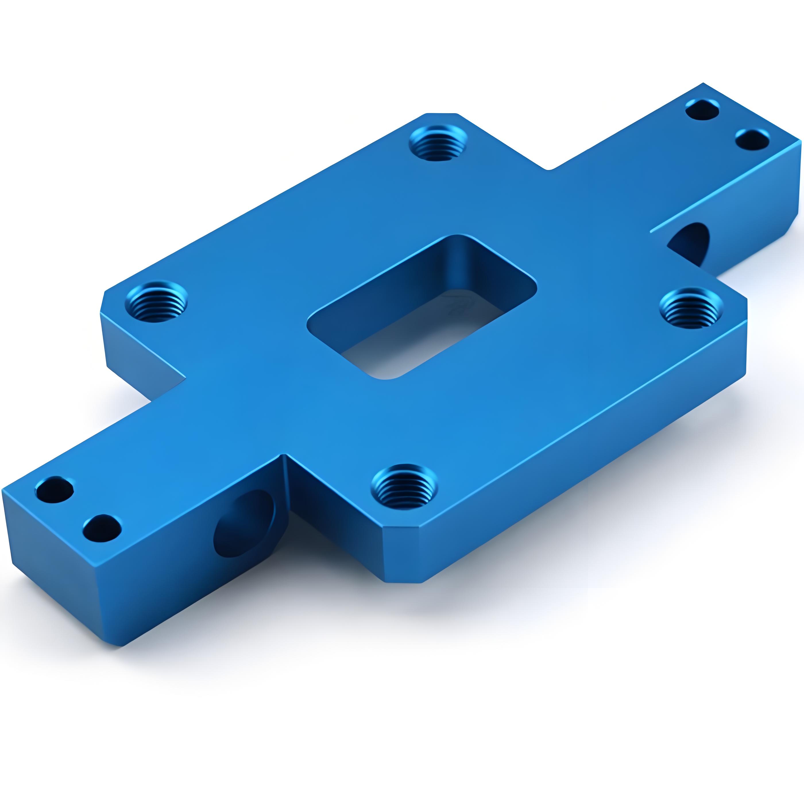
Machining gives three lightweighting tools: pockets, lightening holes, and structural ribs. Pockets remove material from wide, flat, low-stress areas, and their depth is limited by the wall thickness that remains. Lightening holes through webs and non-structural areas reduce weight where the stiffness is carried by the surrounding ribs. Ribs and gussets add stiffness in the plane of the load with less material than a thick solid. The design sequence is to lay out the load path, remove material from the low-stress zones, and add ribs where the remaining structure needs support, checking each step against the deflection and the natural frequency, not just the weight.
Tolerance and Fit at Lower Weight
Lightweighting has a second effect on precision: thin sections flex more during machining and during service, so tolerance couples to stiffness. A thin wall that holds a bearing bore or a locating feature has to be machined with controlled tool pressure and inspected at the service datum, not the relaxed datum. If the part is coated, the coating adds thickness to a section already sized for weight, so the dimensional basis has to be clear. The precision of the joint depends on the thin section holding its geometry under both cutting and load, which is why lightweight robot parts are measured more, not less.
Material Choices Beyond Aluminum
Aluminum is the default for robot arms, but the lightweighting answer sometimes lies in material: aluminum for strength-to-weight, magnesium where even lower density matters and the environment tolerates it, carbon fiber where the load path is composite-friendly, and titanium where heat or corrosion outranks weight. Machining these materials behaves differently, and the fineness of the lightweighting geometry has to match the material’s machinability. A thin section in magnesium machines differently from one in aluminum, and the tooling plan changes with the alloy.
Vibration and Natural Frequency
Speed creates vibration, and stability means the arm’s natural frequency stays above the operating range. Lightweighting changes the natural frequency: remove weight where it matters and the frequency rises, remove stiffness and it falls. The geometry has to be checked against the expected excitation, not just the static deflection, or a pivot belt resonance appears when the arm reaches speed. The manufacturing implication is that the part’s stiffness target is as important as its weight target, and the machining has to preserve the rib and flange structure that sets the frequency.
What to Verify on the Parts
- Weight and weight distribution, so the inertia claim is real.
- Stiffness or deflection at the service datum.
- Critical bores and faces holding tolerance in the thin section.
- Natural frequency against the operating range, where the application runs the risk.
- Surface finish and any coating thickness effect on thin geometry.
Working With a Machining Partner on Lightweight Parts
Lightweight robot components reward a partner who reads the geometry as load paths, not just as pockets to cut: one who flags a thin wall that will flex, a rib that adds machining cost more than stiffness, or a tolerance that a coated thin section cannot hold. The DFM conversation should cover the wall thicknesses, the rib structure, the datum for measuring thin sections, and how tolerance is held under cutting. A partner that optimizes the machining plan to the stiffness target, not just to the file, is the one that turns lightweighting into speed and stability instead of into a resonant part.
Bottom Line
Lightweighting strategies for high-precision robot components work when the material is removed along the real load path and kept where stiffness sets the natural frequency. Pockets, holes, and ribs remove weight, tolerance and coating management keep thin sections precise, and material choice extends the range. The goal is not the lightest part, it is the lightest part that stays stiff and stable at operating speed. Machining that holds both targets, and verifies both on the parts, is what unlocks the speed and stability the design needs.
Natural Frequency and the Resonance Line
The speed story of a robot arm is often a vibration story. Every arm has a natural frequency, and when the operating excitation and the arm synchronize, the arm resonates. Lightweighting changes that number with every pocket. Remove weight where it matters and the frequency rises; remove stiffness and it falls. The geometry has to be checked against the operating range and the excitation, because a resonance at cruise speed defeats every weight saving. A part whose natural frequency sits safely above the operating band is stable by design, and that is the map the machining has to follow.
Wall Thickness and the Tolerance Balance
Thin sections change the tolerance story. A wall thin enough to save weight can flex during cutting, and it can flex under the joint load in service, so the tolerance of a fit or a bore in a lightweight section has to be measured at the service datum, not the relaxed one. A lightweight part that holds its number on the bench and misses it at load is a fixture problem waiting to appear. The machining plan has to account for the stiffness of the thin section, and the inspection has to match the load condition that matters.
Coating and Surface Effects on Thin Geometry
A coating on a lightweight section changes the fit as surely as it changes the finish. The anodize or paint layer adds thickness to a wall already sized for weight, and a close tolerance in a thin feature can land out of spec if the coating is not accounted for. State whether tolerances apply before or after finishing, and where the coating adds measurable thickness, confirm it in the DFM. A thin-part program that treats the coating as a zero-thickness detail is planning a fit surprise.
Machining Strategy for Thin Features
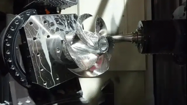
Lightweight geometry rewards a machining partner who reads the thin sections first. A thin web, a tall rib, or a delicate pocket is where tool pressure causes flex and chatter, so the ramp, the tool, and the feed matter more than in a solid part. A partner that machines thin features with light finishing passes and controls the tear-out is one that delivers the lightweight geometry as designed. The strategy is part of DFM, and the quote should reflect it rather than treating the thin walls as a happy accident.
Validating the Lightweight Robot Part
The final validation of a lightweight component is the assembled behavior: the arm that reaches the speed it was designed to reach, the joint that holds its stability at that speed, the resonance that stays out of the operating band. Weight, stiffness, tolerance, and frequency are measured on the actual part, and the prototype test confirms the numbers. The part that passes the assembled test is the part that unlocks the speed and stability the lightweighting promised; the part that only looks light is a prototype, not a solution.
The Production Hand-Off From the Lightweight Prototype
The lightweight prototype does more than prove the geometry; it sets the production route. The pockets, the rib structure, and the thin walls that the prototype validated have to be machinable in production at the target volume, and the prototype is the test of that. Confirm the process that will make the production parts uses the same thin-section strategy, the same material, and the same tolerance basis, so the prototype’s numbers carry to the run. A lightweight design that only the prototype shop can make is a design that has not finished its job.