

What Micron Tolerance Machining Actually Controls
Micron tolerance machining is the production of part features with allowable dimensional variation measured in micrometres, where 1 µm = 0.001 mm. The name invites a misunderstanding: it is rarely a requirement to hold every dimension of a component to a micron-scale number. In practice the term applies to the function-critical features that govern fit, motion, sealing, alignment, safety, or interchangeability—precision bores, mating diameters, sealing faces, hole locations, flatness-controlled surfaces, and concentric rotating features.
A “micron” callout may be a bilateral dimensional tolerance, but it can also be a GD&T control such as position, runout, flatness, perpendicularity, or profile. Each of these is a different manufacturing problem. A bore diameter and a bore position relative to a datum face require different machining strategies and different inspection methods, so the drawing must state which geometric control is actually needed. For example, a runout callout on a rotating feature is verified by rotating the part against a dial indicator, while a profile callout on a sealing face is checked against a gauge that follows the surface contour. Confusing the two at the quoting stage sets up a mismatch between the machining plan and the acceptance test.
For a specific CNC project, 6CProto quotes typical tolerances that can reach ±0.02 mm and may reach ±0.01 mm in some cases. A tighter requirement should be reviewed against the actual feature, material grade, part geometry, quantity, finish, and measurement plan rather than treated as a universal capability. The achievable result depends on part size, material behavior, tool access, fixturing, thermal conditions, surface finishing, and—critically—the inspection method used to verify it. A machinist quoting “±0.01 mm” on a slender aluminum wall without discussing fixturing and temperature has not quoted a process; they have quoted a hope.
Why the Number on the Drawing Is Not Enough
A tight number does not define functional intent. A drawing that writes “±0.01 mm” on several dimensions may still fail to define the datum structure, inspection orientation, mating condition, or geometric relationship the assembly actually needs. GD&T communicates function more effectively when a feature’s location, orientation, runout, or profile matters more than its standalone size, which is why general tolerances (set by ISO 2768 for linear and angular dimensions without individual callouts) and feature-specific tolerances should be assigned to different places on the same part.
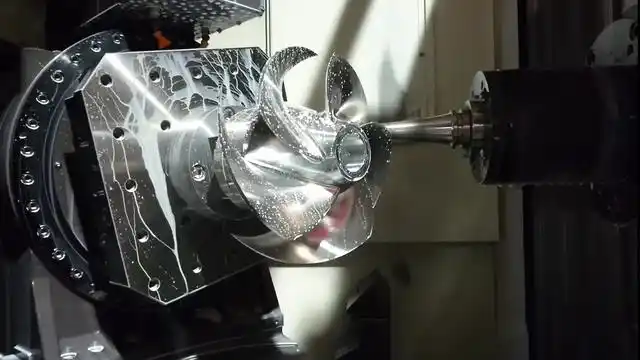
Material and process behavior change the result. Machining forces, residual stress, thermal expansion, burr formation, and deformation under clamping all influence final dimensions. Slender walls, deep pockets, long tools, thin flanges, flexible plastics, and difficult-to-machine alloys may require process changes before a feature can be quoted realistically. A DFM review that asks about these features is doing the work; an instant-quote system that assumes them is taking the risk. The point of the review is not to reject tight tolerances but to separate the features that can hold a micron-scale number from those that cannot, and to propose the machining sequence, stock condition, and finishing order that make the number realistic.
Burrs illustrate the difficulty well. A cutting edge leaving the side of a bore can roll material over the lip, and on a 20 µm tolerance that burr is not a cosmetic detail; it is a dimension. Edge condition, deburring method, and the order of finishing passes belong in the same discussion as the tolerance itself. The same applies to surface finish: anodizing, plating, electroless nickel, polishing, blasting, coating, and passivation alter dimensions, texture, edge condition, and cosmetic appearance, so the drawing must state whether a dimension applies before or after finishing and identify masked, cosmetic, sealing, and contact areas.
Temperature, Fixturing, and the Measurement Chain
The machining setup is only one part of the system. Temperature is a measurable source of dimensional uncertainty: as NIST notes, thermal expansion is an important source of uncertainty in dimensional metrology as required measurement resolution becomes smaller. A part measured at 20 °C and at 40 °C differs in size, so the measurement condition belongs in the tolerance conversation. For aluminum, the difference is large enough that a 100 mm feature changes by a meaningful fraction of a micron per degree; for long components and multi-day production runs, the shop temperature at machining time and at inspection time should be recorded rather than assumed.
Fixturing carries the same weight. A part that flexes under clamping, shifts during a cut, or springs back after release will not hold a micron-level feature regardless of machine specification. The workholding plan—whether a vise, soft jaws, a vacuum table, or a custom fixture—must be matched to the datum features and the cutting forces acting on them. A datum defined on a face that the fixture cannot reference is a datum the process cannot honor, and a thin wall that is clamped hard at setup will not reveal the distortion until the clamps come off.
Inspection is part of the manufacturing requirement, not an afterthought. A part cannot be considered verified merely because it was machined on precision equipment. Critical features may require an agreed inspection method, a measurement datum setup, a sampling plan, report format, and traceability expectations. For a prototype that will move into repeatable production, the drawing revision, material approval, finish sequence, and inspection plan should all be controlled together so the first article and the production run are judged against the same standard.
Plan the Tolerance Budget Before Quoting
The practical route to micron tolerance is a controlled plan, not a tighter machine. Define the part’s function and mating interfaces; prepare a native or neutral-format 3D model plus a controlled 2D drawing with revision level, units, datums, and notes; specify the exact material grade and condition; apply realistic general tolerances to non-critical features; then reserve feature-specific tolerances and GD&T for the dimensions that truly govern function. Submit the RFQ with quantity, finish, required date, and inspection needs, and request DFM feedback before approving a prototype or first article.
The quantity matters to this plan. A one-off prototype can justify a custom fixture, multiple setups, and manual verification because the cost is absorbed once. A pilot batch of fifty parts must amortize the same fixture and inspection effort across the run, which changes the process choice even though the drawing is identical. A production order of thousands may shift the decision to different tooling, a different machine class, or a different finishing route. Stating the quantity and the project stage in the RFQ lets the supplier plan the process that matches the volume rather than assuming the prototype route repeats.
For a controlled prototype scenario, the result is focused effort: identify the bearing bore, datum face, shaft relationship, material, and inspection needs during DFM, then concentrate machining and measurement on the features that control fit instead of tightening every dimension. The same discipline carries into production runs, where in-process checks and documented change control protect the validated process from drift.
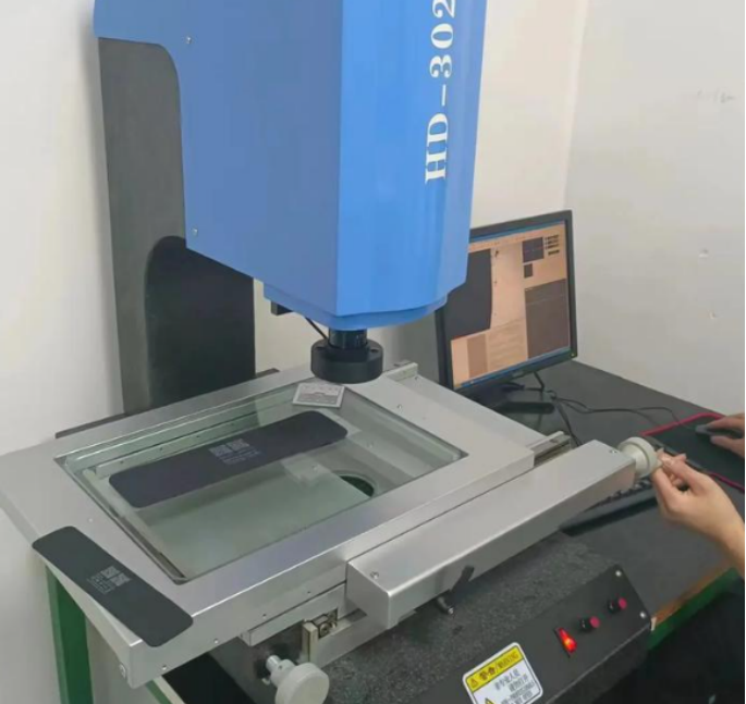
The same plan disciplines the whole supply chain. A released drawing revision, an approved material certificate, an agreed finish sequence, and a named inspection method each carry part of the tolerance risk. If any one of them changes informally—a material substitute, a different anodize thickness, a measurement setup that was not on the report—the micron number stops meaning what it meant on the first article. Change control is not paperwork for its own sake; it is the mechanism that keeps the validated process and the quoted tolerance the same thing from prototype through production.
Use Cases
Functional CNC prototype with critical bearing features
A common pattern is applying a tight tolerance to every dimension, which increases cost without clarifying assembly function. The higher-value route is to identify the bearing bore, datum face, shaft relationship, material, and inspection needs during the DFM review, then focus machining and measurement effort on the features that control fit. The prototype then answers the only question that matters at that stage: does the mating interface assemble and run as intended?
Interchangeability across a batch
When several parts must assemble interchangeably—for example, a housing, a bearing carrier, and a mating shaft—the critical control is not each diameter but the datum relationships between them. If the parts share a measured frame of reference and the inspection is run against that frame, the batch behaves as a system. If each part is inspected independently against its own local datum, the stack-up can drift even though every part passes its own report.
FAQ
What tolerance can 6CProto achieve?
6CProto publishes general CNC tolerance guidance and notes that some CNC projects may achieve tighter values depending on the feature and process. Achievable tolerance depends on part geometry, size, material, fixturing, process, finish, and inspection requirements; confirm project-specific values in the quotation.
How do surface finishes affect precision dimensions?
Finishing can affect coating thickness, edge condition, texture, and final fit. Identify whether critical dimensions are measured before or after finishing and communicate masking, cosmetic, corrosion-resistance, or contact-surface requirements.
Should prototype tolerances equal production tolerances?
They should match when the prototype must validate functional fit, assembly, or performance. For early concept models, applying production-level tolerances to every feature adds cost and delay without improving the decision being tested.
For micron-sensitive components, review the CNC machining tolerances guide and the standards and tolerances overview before submitting your RFQ. See also micro machining services for critical features for the prototype-to-production path. NIST dimensional metrology guidance is a useful external reference on thermal expansion uncertainty.