

How Additive Manufacturing Fits Modern Hardware Development
Additive manufacturing builds parts layer by layer from CAD data instead of cutting material away, and that difference changes the economics of early hardware. A part can be on the machine within hours of a design freeze, no tooling exists until the engineer decides it is worth paying for, and geometry that is difficult or impossible to reach with a cutter is produced as a matter of routine. The trade is real: layer adhesion, surface quality, and per-part cost differ by process and material, so the useful question is not whether 3D printing beats CNC machining, but which process answers the question the team is asking at that moment.
This guide covers the main additive process families, the tradeoffs that appear when a prototype moves toward low-volume production, and the sourcing decisions that determine whether parts arrive on time and to spec. It is written for hardware engineers and procurement leads who need a working decision framework, not a printer catalog.
The Additive Process Families at a Glance
Every additive process follows the same digital pipeline, from solid model to sliced build file, to the print bed, support or powder removal, post-processing, and dimensional inspection. The differences that matter sit in the energy source and the material state, because those set the mechanical properties of the finished part.
Fused deposition modeling (FDM). FDM extrudes thermoplastic filament through a heated nozzle and is the most accessible, lowest-cost route for early geometry checks, simple fixtures, and disposable parts. Layer lines are visible, the material is anisotropic, and parts are weakest across the build axis, so FDM is best treated as validation of shape, not material performance.
Stereolithography (SLA). SLA cures photopolymer resin with a UV laser or light engine. It delivers surface finish and cosmetic detail that other polymer processes cannot match, which makes it the default for visual models, casting masters, and form-and-fit testing. The trade is mechanical: standard photopolymers are brittle, can creep under sustained load, and degrade under prolonged UV or moisture exposure. Engineering resins close part of that gap, but the grade’s data sheet, not the process name, sets the real limit.
Selective laser sintering (SLS) and Multi Jet Fusion (MJF). These powder-bed processes fuse engineering thermoplastic powders with thermal energy or lasers. Because the unsintered powder supports the build, no printed supports are needed, and parts behave close to isotropically. That combination makes SLS and MJF the workhorses for rugged functional prototypes, living hinges, internal ducting, and end-use industrial parts.
Direct metal laser sintering (DMLS) and selective laser melting (SLM). High-power lasers fuse fine metal powder, such as titanium, stainless steel, aluminum, and Inconel, into dense components that can replace cast or machined parts in demanding service. Metal builds carry higher material and machine cost, so the process earns its keep on geometry that machining cannot reach: internal channels, lattices, or assemblies consolidated in one build. Smooth functional faces, threads, and bearing surfaces are printed with stock and finished by CNC machining.
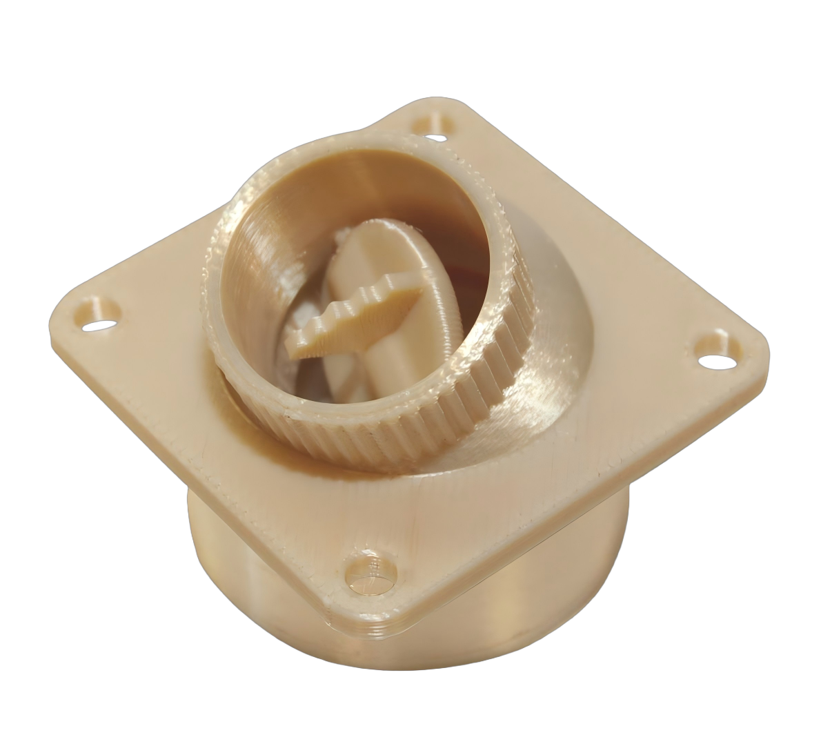
Where Additive Manufacturing Wins in Low-Volume Production
Additive manufacturing is often dismissed as a prototyping-only tool, but its real value appears in production runs that are too small to justify tooling. Injection molding requires steel tooling that takes weeks and costs thousands of dollars before the first part exists. CNC machining has no tooling cost but charges per part for machine time, fixturing, and setup. Additive sits between them: near-zero fixed investment, per-part cost largely independent of geometry complexity, and production lead times measured in days.
- Bridge production. While production tooling is being built, 3D printing can supply functional parts for field trials, certification, or early sales without committing to a second set of molds.
- Low and variable volume. For runs under about one hundred units, additive is generally more economical than machining for complex geometry. As part count grows, the per-part economics of machining and molding take over.
- Mass customization. Because there is no tool, the next part can differ from the last at zero tooling cost, which suits spare parts, small variants, and build-to-order service.
- Consolidated assemblies. A printed assembly replaces multiple machined or welded components, reducing inventory and assembly labor when geometry permits.
Where each process earns its cost
3D printing: complex geometry at low volume, no tooling, days of lead time
CNC machining: tight tolerances at medium volume, isotropic material properties
Injection molding: best per-part cost at high volume once tooling is amortized
Design for Additive: What the Model Must Carry
Additive parts fail early in the supply chain when the CAD model is not built for the process. The most common mistake is sending a mesh file alone. STL describes surfaces but carries no parametric meaning, so wall thickness, internal radii, and secondary machining features cannot be evaluated cleanly, and geometry degrades if the file is converted or modified. For a design-for-manufacturing review, provide solid models in STEP, IGES, or a native CAD format so the supplier can analyze wall thickness, check critical radii, and plan secondary CNC steps without reinterpreting the model.
Wall thickness deserves specific attention. Printed walls below about 0.8 mm in polymer processes become fragile, while walls that are too thick trap heat and distort. Internal channels need escape holes for powder or support removal, and critical threads, bearing journals, and sealing faces should be planned as machined features from the start, with stock added in the model. Each decision is cheap in CAD and expensive, or impossible, after the build.
Process Selection as a Stage-Gate Decision
Product teams rarely pick one additive process for the whole program, and the sequence matters more than any single choice. The common pattern runs through three gates:
- Geometry gate. FDM parts confirm overall shape, interfaces, and assembly fit at the lowest cost. This gate answers what the part looks like and whether it fits.
- Appearance gate. SLA parts give customers and stakeholders an accurate view of cosmetic surfaces, edge sharpness, and finish. This gate answers what the product will feel like.
- Function gate. SLS, MJF, or metal processes validate real stiffness, wear, temperature, and strength before the design is committed to tooling. This gate answers whether the part survives service.
Matching the process to the gate prevents the classic failure of validating function in a process that cannot represent it. A printed geometry check predicts nothing about molded shrinkage, and a resin master predicts nothing about nylon toughness. When the function gate involves load, heat, or tight tolerance, the data should come from the production-representative process or from a machined version of the part that carries the same material state.
Sourcing Additive Capacity Without the Usual Pain
The sourcing failure modes for additive are predictable. The first is quoting the process instead of the part, so the buyer pays for exotic machine time when a standard process would do. The second is assuming that one supplier’s material library matches the grade the application needs; the same printed nylon from two shops can behave differently because of machine condition and parameter choices. The third is treating the printed surface as final: powder-bed parts carry residual powder, metal parts carry a rough as-built surface, and both need post-processing before they behave like the datasheet.
When evaluating an additive supplier, ask what processes run in-house, which material grades are stocked rather than merely listed, what inspection equipment and reports accompany a build, and what happens to critical features that need secondary machining. 6CProto operates 3D printing services alongside CNC machining, so printed critical features can be post-machined in the same facility. The 3D printing materials overview documents which polymer and metal families are available before quoting, and the process comparison in “FDM vs. SLA vs. SLS: Which 3D Printing Process Fits Your Part?” helps choose the family first.
Dimensional Accuracy and the Limits of Raw Prints
Commercial polymer processes such as SLS, MJF, and SLA typically hold tolerances of approximately plus or minus 0.1 to 0.3 mm on standard parts, with the actual value depending on part size, aspect ratio, and cooling dynamics. Metal printing via DMLS or SLM starts from a different place: raw overlay is often tighter per unit of size, but residual stress and surface roughness prevent raw builds from meeting the tolerance of a machined bearing surface. The result in practice is a hybrid: critical features are printed oversize and machined in a secondary CNC step.
| FDM | Plus/minus 0.3 to 0.5 mm on standard geometry; visible layer lines |
| SLA | Plus/minus 0.1 to 0.3 mm; best cosmetic surface of the polymer family |
| SLS / MJF | Plus/minus 0.1 to 0.3 mm; isotropic behavior, no printed supports |
| DMLS / SLM | Raw build may approach metal tolerances; critical faces require post-machining |
These are reference bands, not guarantees, and the tolerance callouts use terminology consistent with the general principles defined in additive manufacturing standards such as ISO/ASTM 52900 (ASTM standards). A number on a datasheet never replaces a DFM review of the actual part.
FAQ
Does 3D printing always need support structures?
No. Powder-bed methods such as SLS and MJF need no printed supports because the unsintered powder holds the part in place, while FDM and SLA generally need them for overhangs. Choosing the process for the geometry removes a whole class of support-related issues.
Can a printed part replace an injection-molded production part?
Only with the right material-process pairing. Glass-filled polyamide and PEEK parts from powder-bed processes approach molded performance for many functional roles, though fatigue and long-term behavior still need verification. Parts that require molded surface class, tight draft, or very low per-unit cost still transfer to molding when volume justifies it.
Why do critical tolerances get machined after printing?
Because the printed surface is not the final surface. Powder-bed parts carry roughness and residual porosity at the micron scale, metal builds carry surface roughness and residual stress, and thermal shrinkage shifts dimensions. Post-machining turns a rough functional blank into a bearing surface or thread that passes inspection.