

Every micron matters in precision manufacturing. Aerospace bracketry, medical device components, consumer electronics housings, and automotive drivetrain parts all carry tolerances on surfaces and positions that a micrometer-style measurement has to verify, not assume. For buyers and engineering teams sourcing machined parts, the question is never only what the drawing says; it is how the part is proven against the drawing at the time it ships. That is the job of coordinate measuring machine (CMM) inspection. This article explains what CMM inspection is, why it matters across prototypes and high-volume runs, what it does and does not catch, and how to require it in an order so the inspection report is evidence, not theater.
What CMM Inspection Is
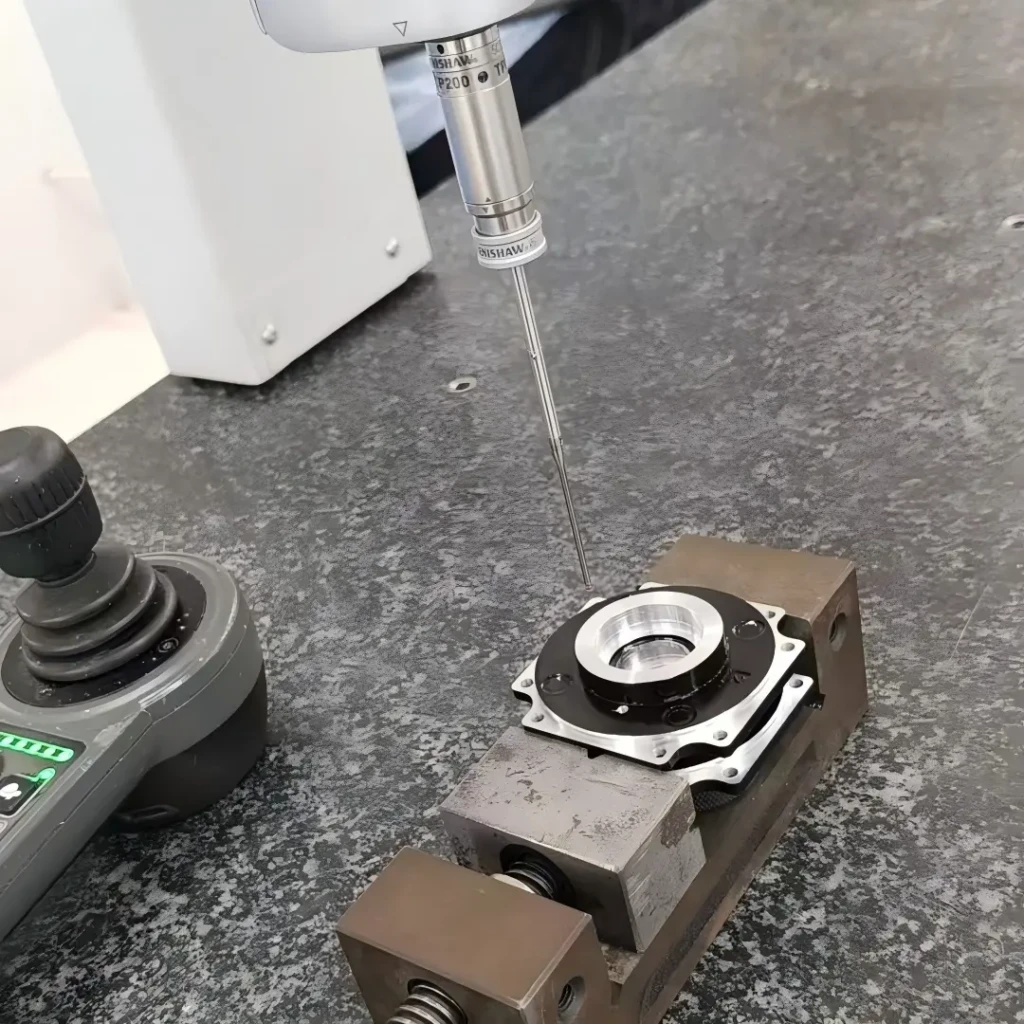
CMM inspection uses a coordinate measuring machine to measure the physical geometry and dimensional features of a part in three dimensions. The machine positions a probe, a laser, or an optical sensor at measured coordinates on the part, compares the readings against the CAD model or the drawing, and reports the deviations. A CMM verifies what a caliper or a plug gauge cannot: the relationship between features across the part, position relative to datums, and form across a surface. On a bracket with four mounting holes that must land relative to each other, or a housing whose bore must be positioned to a face, the CMM is the instrument that proves the assembly geometry.
Why CMM Inspection Matters for Custom Parts and Prototypes
In a prototype, the CMM report is the proof that the design translated into geometry correctly: the first article either measures inside the tolerance band or it does not, and the report tells you which. In custom parts, CMM inspection closes the gap between what the drawing promises and what the process delivered, catching positional and form errors that a dimension sheet would miss. The value is not in the three-letter acronym; it is in tying the measurement to the datum and the critical feature. A CMM report that lists measured deviations on the critical features, with the fixture and the datum stated, is the document a buyer can trust against the drawing.
How CMM Inspection Fits High-Volume Manufacturing
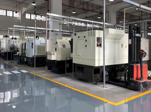
High-volume production inverts the value of CMM inspection. In prototyping, the CMM verifies a few parts thoroughly; in production, it verifies the process on a schedule. The first article is measured completely, and then CMM checks run on a defined sampling plan through the run, re-verifying the critical features that are most likely to drift. A well-run program pairs CMM inspection with an in-process gauge: the gauge catches the trend cheaply, and the CMM re-proves the geometry at defined intervals. The result is a traceable chain from the first article to the middle and end of the run, which is exactly what an auditor or a quality engineer wants to see.
What CMM Inspection Measures, and What It Does Not
A CMM measures geometry: position, flatness, concentricity, runout, and profile against CAD. It does not measure surface finish in the way a roughness gauge does, and it does not test material properties. Confusing the instruments is a fast way to write a spec that cannot be met or an inspection that misses the real risk. Use a CMM for dimensional and positional verification, use a roughness gauge for finish, and use material certificates for chemistry. Each instrument has a job, and the drawing should state which one verifies what.
The Role of the First Article
The first article is where CMM inspection earns its reputation. The critical features are measured completely on the first parts, against the drawing and the datum, and the report shows the actual deviations. This sets three things at once: the part is proven, the fixture and the datum are locked for the run, and the expected measurement band is established. A first article without a CMM report on the critical features is a part that has net yet been accepted; the report is what makes the rest of the run meaningful.
The CMM Report: What to Look For
The value of CMM inspection is only as good as the report. A useful report names the critical features, the datum, the nominal value, the measured value, the deviation, and the tolerance for each. It states the fixture and the measurement method, so the number is reproducible. A report full of pass checkmarks without values is a form, not evidence. When you order CMM inspection, specify the features to be measured, the report format, and the criteria: these three decisions decide whether you receive proof or decoration.
How to Put CMM Inspection in an Order
- Name the critical features and the tolerance each must meet.
- State the datum and the GD&T on the drawing, so the CMM has a reference.
- Specify a complete first-article CMM report with measured values.
- Define the sampling and the re-use of CMM checks through a production run.
- Confirm the measurement method and the report format at RFQ.
Bottom Line
CMM inspection proves dimensional and positional geometry against the drawing, and it matters in prototypes and production because it verifies relationships no hand tool can. Use it on the critical features, tie it to a datum, publish the measured values, and pair it with in-process gauging on long runs. A part with a CMM report is a part that has been proven; a drawing is only a promise. In precision manufacturing, the machine cuts the part, and the CMM decides whether to believe it.
Reading a CMM Report Like an Engineer
When a CMM report arrives, the reading order matters. Start with the datum and the method, because everything else is relative to them; then check the measured values against the tolerance, not the pass symbol. A measured value that sits near the edge of the band is not the same as one in the middle, even when both pass. Then look at the trend across parts: a value that is in the middle on the first article and drifting toward the edge by the third is a process moving, and it should be caught before it exits the band. Engineers read the numbers and the movement; everyone else reads the verdicts.
The Cost of CMM Inspection and How to Budget It
CMM inspection carries a real cost, and it belongs in the quote, not discovered later. The cost is driven by the number of features, the complexity of the measurement, the fixture and setup time, and whether the data goes on a sampling plan or a full first article. Budget the inspection the way you budget the machining: the feature you want proven is the feature you pay for. A buyer who hides the inspection requirement until after quoting gets a surprise and a fight; one who states it at RFQ gets a price and a plan. The inspection is part of the part’s cost, and it should be treated that way.
When CMM Inspection Is Worth the Investment
CMM inspection pays when the part carries positional or form requirements that assembly depends on, when the volume makes a drift expensive, or when the application, aerospace, medical, or automotive, demands the evidence. A simple bracket whose features are cosmetic does not need a CMM; a housing whose bores must align across two halves does. The honest test is what failure costs. If a bad position means a scrapped assembly, a failed seal, or a rejected lot, the CMM is cheap. If failure costs a scrap part, a gauge may be enough. Spend the inspection where the risk is.
How to Ask a Supplier About Its CMM Capability
The way a supplier talks about CMM tells you whether it runs a real inspection program. Ask which machine and probe it uses, how it sets the datum, how it writes the report, and how it acts on out-of-tolerance readings. A supplier that names the method and the corrective loop is describing a system; one that only says ‘we have a CMM’ is listing equipment. The conversation should also cover calibration: how often the machine is gauged and what the records show. The right supplier treats the measurement as part of the process and can show you the chain from the instrument to the part.
Where CMM Fits in a Machining Workflow
The CMM is not a separate step at the end of the line; it is part of the machining workflow. A CNC machining program that plans the CMM at the design stage, specifies the datum on the drawing, and verifies the first article against it runs a tighter loop than one that inspects after the fact. The same discipline applies across a standards and tolerances framework: the feature, the tolerance, and the inspection are defined together. The shop that treats measurement as part of the process, not as a checkpoint, delivers parts that assemble the first time and repeat to the same number.
Getting the Most From an Inspection Report
Ask the supplier to explain what the report proves and what it leaves open. A CMM report proves the measured features against the drawing; it does not prove the finish, the material, or the heat treatment. Pair the CMM data with the material certificate and the surface measurement where the part needs them, so the evidence covers the whole part. The complete picture is the one that survives a review or an audit, and the buyer who knows the limits of each measurement builds a full proof out of the right pieces.
A CMM is an excellent geometrical measuring machine, but it does not measure everything by itself. It does not measure surface roughness the way a profilometer does, and it does not confirm the chemistry of the material. A complete quality story pairs CMM geometry with surface finish measurement and material certificates, so the evidence matches the claims. The drawing should say which instrument verifies which feature, because a geometry report cannot stand in for a material certificate, and the reverse is just as true. Buyers who understand the limits get reports that fit together into a proof; buyers who overtrust one instrument get a single number doing too much work.
The other limit is the report itself. Values, datums, methods, and tolerances make a CMM report checkable; a summary sentence makes it a conclusion. When a shop sends a report with values, it is inviting audit; when it sends a pass mark, it is asking for trust. The difference is the whole game in precision work.
Related Capabilities and Guides
For the service scope and the material and tolerance details behind this article, see the CNC machining, the standards and tolerances, and the advanced CMM inspection. The first article of your order ties the design to the measured result, and the same drawing, datum, and inspection discipline carry across the program.