

What Fabricated Metal Assemblies Are
Fabricated metal assemblies combine multiple metal components—cut, formed, machined, and welded—into ready-to-use sub-assemblies. They simplify a supply chain by replacing many part numbers with one, while improving quality, fit, and integration. A fabricated assembly is a multi-part structure built from individual metal components that are cut, bent, machined, welded, fastened, and finished into a single functional unit. It arrives as a ready-to-use sub-assembly, designed to bolt into the product with minimal extra work, wiring, or adjustment on the line.
On the factory floor these are “mini-products” rather than loose parts: welded frames with mounting plates, sheet-metal housings with machined brackets, or integrated chassis with threaded inserts and captive hardware. The practical pattern is a laser-cut mild steel base, bent stainless brackets, and aluminum machined plates combined in one assembly. The value of the form is not the parts; it is the fixture-built relationship between them.
Where Integration Saves More Than Part Cost
Shipping the assembly to the line instead of a bag of parts shifts value-added work upstream, where fabrication and integration are optimized around fixtures, jigs, and specialized skills. Although the assembly’s unit price may look higher than the sum of raw parts, savings appear in fewer pick-and-place steps at final assembly, less rework from misaligned parts, and faster troubleshooting because sub-assemblies arrive pre-tested. The classic hidden tax is line operators spending minutes shimming or grinding for fit; holding critical interfaces in jigs and checking key datums in one go removes that variation from the plant floor.
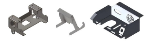
The cost conversation should be framed at the assembly level, not the part level. Fewer purchase orders, vendors, and SKUs reduce supply chain overhead; less inventory sits between workstations; and a single accountable partner replaces several handoff points that can fail. The trade is real: the buyer carries fewer SKUs, and the supplier carries more responsibility, which is the exchange most OEMs prefer once they have seen it work.
Common Metals, Processes, and Joining Methods
The most common metals in fabricated assemblies are mild steel, stainless steel, aluminum, and sometimes high-strength low-alloy steels. These are combined through laser cutting, bending, CNC machining, tube forming, MIG/TIG welding, riveting, and bolted joints, often with powder coating or plating as final finishes. The main joining methods are welding (MIG/TIG), mechanical fastening (bolts, rivets, PEM inserts), brazing, and occasionally adhesive bonding. Welded joints are strong and rigid; fasteners are rework-friendly; brazed or bonded joints suit thin-gauge or dissimilar-metal scenarios. A common mix is welding a core structure for stiffness, then bolting on removable access panels or interface plates, with joints designed so they are accessible for both the joining process and quality checks.
Design Rules: Datums Before Details
Assembly-level tolerances behave differently from part-level tolerances. Mismanaged accumulation of small part-level deviations causes misalignment at the assembly level: holes that do not line up, shafts that bind, or covers that will not close. The datum strategy dictates how those tolerances “add up” and where the physical reality of the assembly is controlled. Engineers should cluster critical tolerances in one control frame of the assembly instead of spreading tight specs across every joint: build a robust reference structure, then relax non-critical features.
Slotted holes, tab-and-slot features, and self-locating joints allow repeatable alignment without heroic effort or custom gauges. The assembly-level drawing or model should define primary, secondary, and tertiary datums, and fixturing and inspection should be built around those datums—for example, where a bearing seat meets a motor shaft or a rail meets a linear guide. Design for efficient integration by minimizing unique parts, aligning joints with natural load paths, standardizing hole patterns, and designing joints that are easy to fixture, weld, or bolt. Avoid floating interfaces, and specify datums that are accessible during both fabrication and final inspection.
Quality and Inspection at the Assembly Level
Inspection typically includes dimensional checks on key datums, gauge-based fit checks, weld visual inspections, and sometimes CMM verification or NDT for critical welds and load-bearing interfaces. Critical interfaces are validated against assembly-level tolerances, not just part drawings. A frame whose mounting holes are each within part tolerance can still tilt because the datums referenced different physical surfaces; the assembly check catches that, the part check does not. For high-stress and safety-critical applications, fabricated assemblies are viable when the joining method, weld schedule, material grade, and inspection requirements are defined and verified—the load path and the joint pedigree are the difference between a structural assembly and a decorative one.
Ownership: Who Decides What Gets Integrated
Fabricated assembly decisions should be jointly owned by design engineering, manufacturing or operations, and supply chain. Engineering defines function and the “must-hold” dimensions and loads; operations maps where the sub-assembly plugs into the line; procurement balances commercial terms and supplier capability. In successful programs, a lead mechanical engineer defines the interfaces, operations confirms the assembly flow is efficient and safe, and procurement brings the partner into early discussions. That triad makes it far easier to decide which components should be integrated upstream and which should remain separate for late customization or serviceability.
Fit in a One-Stop Manufacturing Model
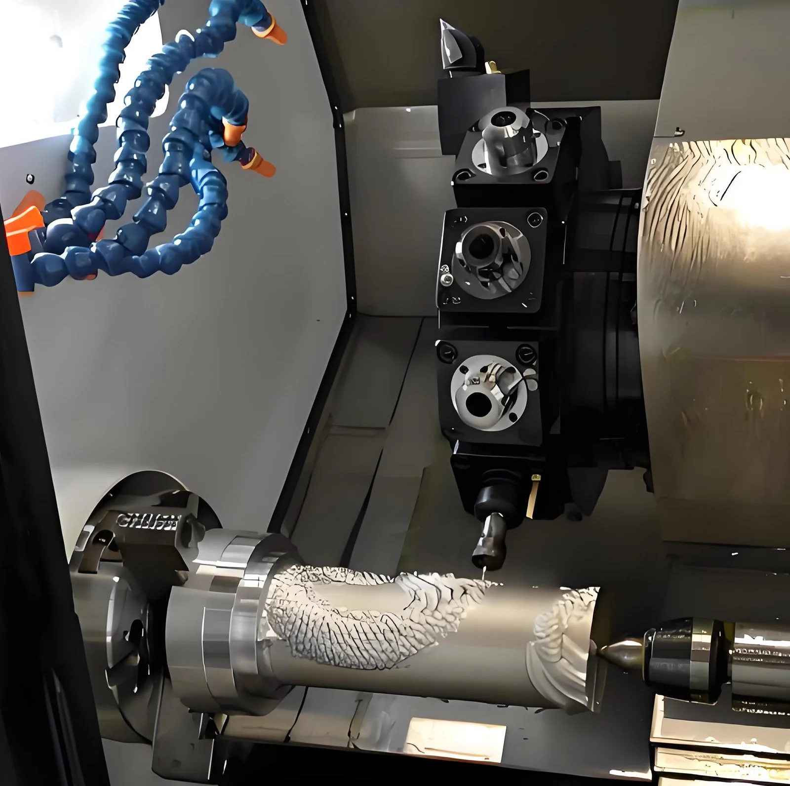
Fabricated metal assemblies sit at the intersection of sheet metal, CNC machining, and turning capabilities. Instead of the buyer coordinating three or four vendors, one network cuts, bends, machines, turns, and welds the metal parts, then delivers a complete assembly with tight fit and finish. Because the full chain is owned, features can shift between sheet metal and machining when that improves cost, lead time, or performance—something rarely available when every process sits in a different factory.
DFM at the Assembly Level
Assembly-level DFM asks different questions than part-level DFM. Where does the load actually travel? Which joint is structural and which is a cover? Which dimensions must hold in the assembled condition and which relax after welding? The supplier should flag weld shrinkage and distortion around long seams, heat-affected zones on thin material, and the sequence that minimizes the effect of welding on critical datums. A bracket welded to a frame pulls toward the weld; if the drawing does not say whether the critical hole is re-machined after welding or positioned to survive the distortion, the assembly inherits the result either way. Early DFM catches these decisions before fixturing is committed, which is why the most productive review happens before release to production.
Fixture design is where assembly quality is paid for. A weld fixture that references the same datums as the final inspection, holds the parts against the welding distortion instead of away from it, and leaves the critical interfaces accessible for gauging converts a fabrication step into a quality step. The same principle applies to fastener assembly: a drill and assemble fixture that locates holes from the control frame ensures every unit is built the way the prototype was, rather than the way the operator happened to reach. Fixtures carry cost, but on a repeat assembly that cost amortizes quickly against rework, scrap, and line shimming.
Design Changes and Supply Chain Risk
Fabricated assemblies support design changes well when the assembly is modular and uses standardized components. Because there is no expensive casting or stamping tooling, bracket shapes, hole patterns, and reinforcement features can be adjusted at relatively low rework cost compared with tool-based processes. Clear revision control and early collaboration minimize disruption and requalification effort. Outsourcing complete metal sub-assemblies can reduce supply chain risk by consolidating multiple vendors and steps into a single accountable partner, simplifying scheduling and reducing handoff points. It requires a supplier with real integration competence rather than a broker, and the first few builds should be treated as DFM testbeds where requested shop-floor adjustments are tracked.
When to Move From Loose Parts to Assemblies
It makes sense to move from loose parts to full assemblies when the line is spending too much time aligning components, scrap or rework rates are high, or the product mix is complex and changeovers are painful. As volumes grow and designs stabilize, integrating parts upstream yields increasingly better returns. A phased approach works well: start with a few pain-point assemblies such as frame structures or complex brackets, measure the impact on build time and quality, then scale to enclosures with hinges installed or motion modules with shafts and bearings pre-fitted.
Fabricated assemblies can also improve product performance directly: a fixtured and stress-relieved welded frame is stiffer, holds alignment longer, and controls vibration better than the same frame assembled piece-by-piece in the field. Gussets, ribs, and multi-plane joints are practical when the supplier controls the fixture and the weld sequence, which is why equipment built this way tends to hold calibration longer and behave more predictably in service.
FAQ
What information do I need to request a quote for fabricated metal assemblies?
You should provide 3D CAD models, assembly and part drawings, material and finish specs, annual volume estimates, load and environment details, and any critical interfaces or regulatory requirements.
Can I mix sheet metal, machined, and turned parts in one assembly?
Yes. Fabricated metal assemblies often combine laser-cut sheet, bent brackets, CNC-machined plates, and turned shafts. A one-stop partner like 6CProto can integrate these into a single, ready-to-install unit.
How are fabricated assemblies inspected to ensure quality and alignment?
Inspection includes dimensional checks on key datums, gauge-based fit checks, weld visual inspections, and sometimes CMM verification or NDT. Critical interfaces are validated against assembly-level tolerances, not just part drawings.
Explore sheet metal fabrication, the fabricated assemblies service, and the sheet metal tolerances guide to prepare your RFQ. ASME standards provide an external reference on fabrication, welding, and dimensional practice.