

Five-axis machining is often promised as the answer to tight tolerances and great finishes on complex parts. The honest version is more qualified: five axes make complex geometry possible, and they hold their tolerances and finishes well, but the numbers depend on the surface, the strategy, the fixture, and how the part is inspected. A sculpted surface and a flat face live by different rules, and expecting machining-tight numbers on a freeform surface without the inspection to back it is a setup for disappointment. This article explains what tolerance and surface finish to expect from 5-axis machining on complex surfaces, what drives the achievable number, and how to specify it so the part and the inspection agree.
Why Complex Surfaces Behave Differently
On a flat face, tolerance is about position and flatness, both measured against a datum. On a sculpted or freeform surface, tolerance is about the whole surface following the model within a band, and finish is about how smoothly the toolpath traced it. The achievable numbers depend on the interpolation, the tool stepover, the machine’s dynamic accuracy, and the fixture that holds the part while all axes move. The same machine can hold different numbers on different surfaces, so a blanket tolerance for a complex part is usually the wrong spec.
What Shapes the Achievable Tolerance
Several variables set the band on a complex surface. The machine’s dynamic accuracy matters, because all five axes are moving under load and holding position continuously. The CAM interpolation decides how faithfully the toolpath follows the model. Tool deflection in deep or thin sections adds error. The fixture and datum decide whether the surface lands where the assembly expects it. And the inspection method decides what the tolerance actually measures: CMM probing a grid, optical scanning, or contact measurement each read the surface differently. State the tolerance with the inspection basis, or the number has no meaning.
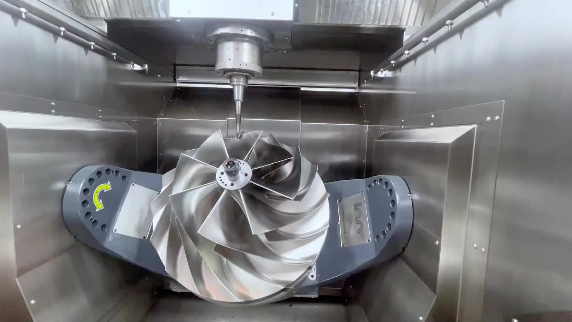
Surface Finish on Contours
Finish on a sculpted surface is set by the toolpath strategy: the stepover between passes leaves cusp height that becomes roughness, and the finishing pass smooths it. A fine stepover gives a smoother surface at the cost of cycle time; a coarse one leaves visible scallops. The achievable Ra or surface profile depends on the stepover, the tool, the material, and whether a final finishing pass was used. For a functional or optical surface, specify the finish with a basis, and confirm the strategy that will hit it. Aesthetics alone is not a spec.
Where 5-Axis Earns the Better Number
On a surface that can only be reached with continuous tilt, five axes produce a better finish than any fixed-axis strategy, because the tool stays engaged instead of rubbing. On a deep cavity, the short rigid tool that simultaneous motion allows deflects less and cuts truer. That is where the machine’s tolerance and finish really beat the alternatives. On a flat, simple surface, the five-axis machine has no advantage, and its dynamic motion may even hold a looser number than a locked-axis cut. Expect better numbers where the geometry needs the fifth axis.
How to Specify Tolerance on a Complex Part
Break the part into the surfaces that matter and give each its own requirement. A sealing face gets a position and form tolerance with a defined inspection; a cosmetic surface gets a finish requirement; a locating face gets a datum-based position tolerance. A single ‘hold everything to X’ callout on a complex part either forces over-inspection or guarantees a fight. Write the tolerance per feature, with the datum and the inspection method, and let the machine hold what each feature needs.
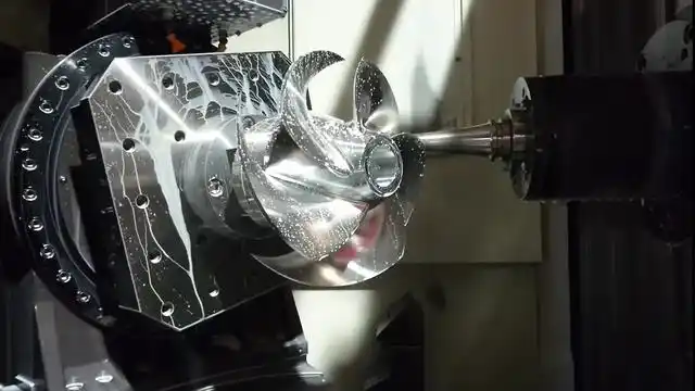
The Role of the First Article
On a complex 5-axis part, the first article is the contract. It is where the surface tolerance, the finish, and the inspection method are proven against the model, and where the fixture and the datum are locked for the run. A first article that measures the critical surfaces with the agreed method, and shows the values rather than checkmarks, is the evidence the rest of the program runs on. Without it, a complex part is a promise repeated until one fails.
What to Confirm With the Supplier
- The tolerance and finish per critical surface, with the inspection basis.
- The CAM strategy: stepover, finishing pass, and simulation.
- The fixture and the datum for the critical surfaces.
- How the first article measures the complex surfaces.
- What is achievable on the specific geometry, not a brochure number.
Bottom Line
5-axis machining delivers its best tolerance and finish on the surfaces that need the fifth axis: sculpted, deep, and contoured geometry machined with constant tool engagement. Expect the numbers to depend on the strategy, the fixture, and the inspection, not on a badge. Specify tolerance and finish per critical surface, with the datum and the measurement basis, and prove it on the first article. That is how a complex part gets real numbers instead of rounded ones.
The Stepover and the Cusp: Where Finish Is Decided
Surface finish on a sculpted surface is decided by the toolpath stepover before any polishing is considered. Each pass leaves a small cusp between passes, and the cusp height becomes the roughness of the surface. A fine stepover gives a smoother nominal surface and costs cycle time; a coarse one leaves visible scallops that a cosmetic finish cannot hide. The finishing pass that runs at near-zero stepover smooths the cusp and sets the final texture. The achievable Ra or surface profile is a product of this strategy, so a finish callout should come with a stepover and finishing-pass plan that can actually reach it.
Tool and Fixture Effects on a Moving Surface
All five axes moving means the fixture and the tool are part of the accuracy. A part held so it can flex, or a tool too long for the reach, adds error to a surface that is already being machined dynamically. The fixture has to support the part rigidly through the whole toolpath, and the tool has to be short and stiff enough to reach the deep features without deflecting. The inspection then measures the result of the whole chain, not just the machine. Confirm the fixture and tool strategy with the supplier when the surfaces are critical.
Measuring a Complex Surface: The Basis Is the Spec
A complex surface tolerance means nothing without the measurement basis. A CMM probe grid, an optical scan, and a form gauge each read the surface differently, with different resolution and different datum assumptions. The drawing should state which method, what grid or sampling, and what the acceptable deviation is against the model. Two shops measuring the same part with different methods can report different pass/fail results, and without the basis, the tolerance is an argument waiting to happen. Fix the method with the spec.
Expectation Setting: The Quote Should Name the Numbers
The quote for a complex 5-axis part should name the achievable tolerance and finish for the specific surfaces, not a brochure range. Ask the supplier to state the expected surface deviation, the finish, and the inspection method for your geometry and material. If the number cannot be stated, the part needs a first article to set it. The supplier that names a realistic figure and stands behind it is the one whose complex surface will measure true.
The First Article Is the Contract
On a complex 5-axis part, the first article is the point where the promise becomes a measurement. The critical surfaces are inspected against the model, the finish is verified, the fixture and datum are locked, and the report carries the values. The rest of the run then uses the confirmed setup. A first article that shows the actual surface measurements is evidence; one that repeats the brochure is decoration. Choose the supplier who verifies, because a complex surface is only as good as its proof.
The Finish Basis and the Toolpath Trade
When a finish number is on the drawing, the toolpath has to be scheduled to reach it. A fine stepover produces a smooth surface at a cycle cost, and a finishing pass adds the final texture. The trade is real: a high-finish requirement on a large complex surface can double the program time, and the quote should reflect it. Confirm the finish target, the stepover plan, and the time impact, so the surface spec and the schedule are both honest. The supplier who names the trade is the one whose number will measure.
When Tolerance Is About the Fit, Not the Surface
On a complex part, the tolerance that matters is sometimes about how the surface fits its neighbor, not how smooth it is. A sealing face must seal; a mounting face must sit flat; a critical relationship must hold position. Distinguish the fit-critical tolerance from the finish-critical one, because they are set and inspected differently, and applying a finish requirement where a fit is needed, or vice versa, forces the wrong trade. Call out which surfaces carry fit and which carry finish, and the machining and the inspection follow.