

Five-axis machining is a capability that is easy to underuse and easy to overuse. The machine can tilt and rotate, but the part earns that capability only when the geometry needs it: setups reduced, reach enabled, or a surface machined in one pass. The design rules are simple to state and hard to over-apply: cut the part to fewer setups, keep the tool short and stiff, and let the angle serve the surface. This article explains the geometry that actually benefits from five axes, the design rules that make it work, and when a simpler route is the better answer.
The Geometry That Earns Five Axes
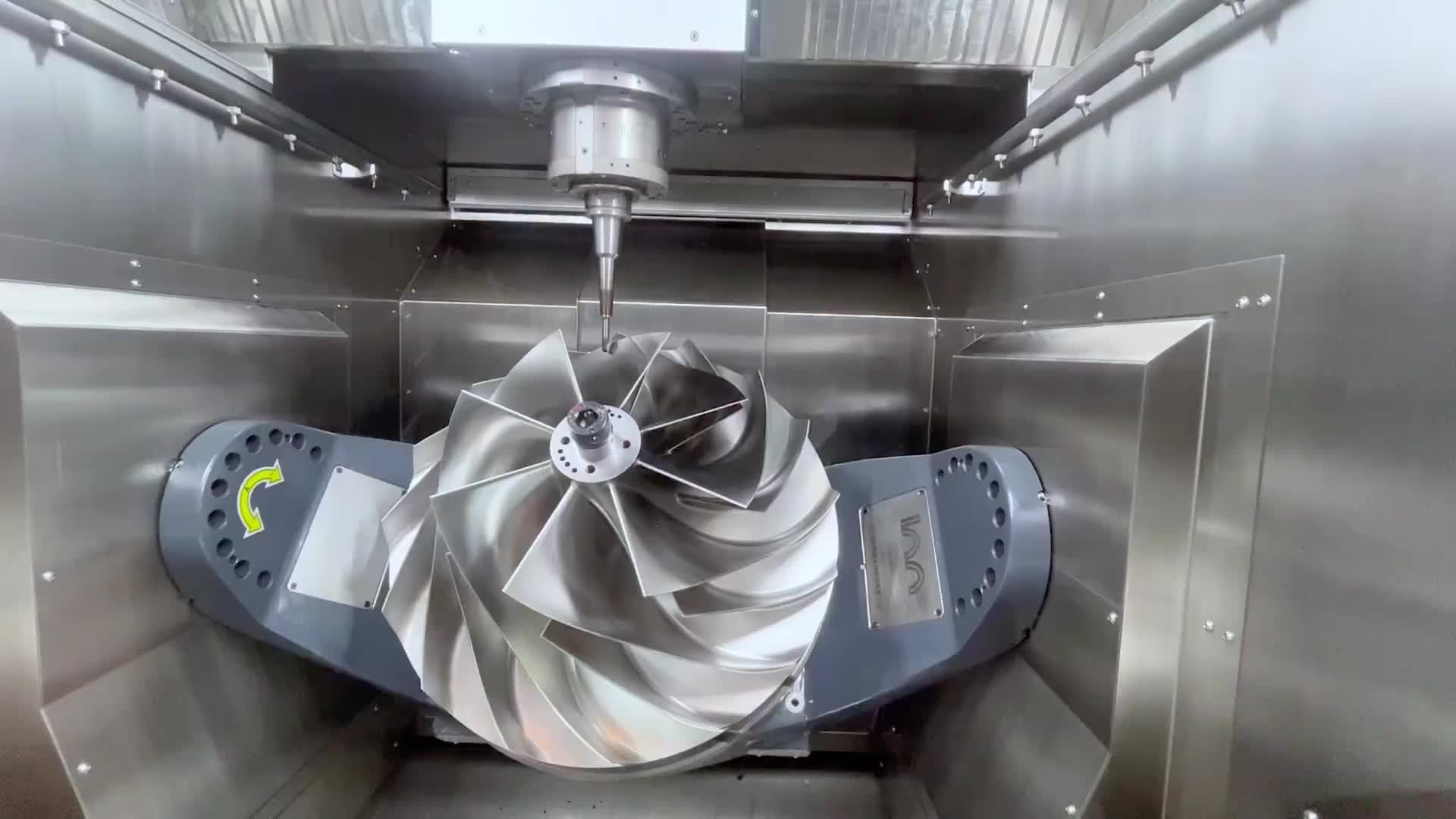
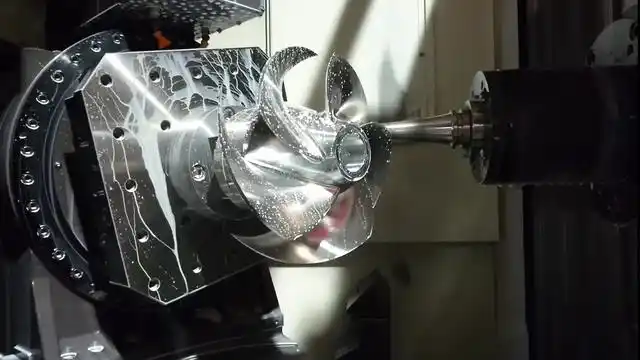
Five axes earn their cost on geometry that needs continuous tool engagement or multi-face reach in one setup: impellers, sculpted bodies, deep cavities, and parts with features on several faces that must stay aligned. The two axes add tilt, so a continuously curved surface can be machined with the tool perpendicular, and an undercut can be reached without re-fixturing. The test is simple: if the part needs fewer than four or five setups on a three-axis machine, or if a single fixed tool angle cannot do the job, five axes may not be needed. The geometry has to demand the fifth axis.
Design Rule 1: Machine in Fewer Setups
The first rule is to design for fewer setups, because every re-fixture stacks error and costs time. Five axes shine when a part that would need five or six three-axis setups is machined in one. That means designing the features so they can be reached from the machine’s tilting axes in a single program: orient the datum, plan the reachable faces, and keep the critical relationships in one setup. If the design forces re-fixtures anyway, the five-axis advantage shrinks and the cost shows.
Design Rule 2: Keep the Tool Short and Stiff
The second rule is tool length. Five axes allow the machine to tilt into a feature, so a deep pocket or undercut can be cut with a short, rigid tool instead of a long, flexible one. The design should favor geometry that a short tool can reach: generous approach angles, staged steps into deep features, and no corners that demand an impossibly long reach. Tool deflection is the silent accuracy killer, and short tools are how five axes avoid it. Design the pockets so the tool stays short, and the machine stays accurate.
Design Rule 3: Let the Angle Serve the Surface
The third rule is that tilt should be used to hold the tool perpendicular to the surface, not for its own sake. On a constant-angle face, a fixed axis works; on a continuously curving surface, the tilt keeps the cutting edge engaged and the finish consistent. The design benefit is the surface quality and the tool engagement, so the geometry should be shaped to reward a perpendicular tool. A part that tilts the machine but never changes the engagement angle is paying for capability it does not use.
The Reach and Feature Size Balance
Five axes do not remove tool geometry limits. Small features in a large part can still force a long tool, and sharp internal corners still need a radius, because the tool has a physical size. The design rule is to confirm the minimum reachable feature size relative to the part: features scaled to the tool are machinable, features lost in a large part force compromises. The DFM conversation should flag where the geometry meets the tool limit, because five axes cannot cut what no tool can reach.
When the Five-Axis Rule Is a Rule of Less
The honest design rule is sometimes to use fewer axes. A simple part on a five-axis machine costs more per hour and more in programming, with no benefit. The geometry test saves money: if the part is two-faced and prismatic, a three-axis machine or 3+2 positioning is the right answer, and the five-axis machine is reserved for the parts that need it. Overusing the capability is a design and quoting error, not a virtue. The rule of less is as important as the rule of reach.
Design Rules at a Glance
- Design for one setup and fewer re-fixtures.
- Keep the tool short and stiff with staged reach.
- Let tilt serve the surface engagement and finish.
- Match feature size to tool reach, with radii.
- Use 3-axis or 3+2 where five axes are not needed.
Bottom Line
5-axis machining benefits the geometry that needs continuous engagement, multi-face reach, and fewer setups, and the design rules make that benefit real: fewer re-fixtures, short stiff tools, tilt that serves the surface, and features scaled to reach. The capability has to be earned; a simple part on a five-axis machine is a premium in search of a reason. Match the geometry to the fifth axis, respect the tool limits, and use the simpler route where it fits. A part designed for five axes machines like it is supposed to; one that just happens to spend more per hour pays for a badge it never needed.
Related Capabilities and Turning the Advice Into an Order
The discipline in this article holds best inside a wider capability set, where the drawing, the datum, and the inspection travel with the part across the program. The 5-axis machining CNC machining pages cover the service scope and the tolerances that apply, and the first article ties the design to the measured result. The concrete next step is to send a drawing with the critical features and the datum stated, ask for the DFM review, and request the first-article report with values, so the advice becomes a controlled order instead of a good idea.
The Surfaces That Make a Part Expensive
In 5-axis work, the expensive surfaces are the ones that need the tilt: the continuous curves, the deep cavities, and the undercuts that no fixed axis reaches. The design should concentrate its tolerance and finish budget there, and machine the flat, simple features with the cheaper strategy. A drawing that spreads precision evenly over the whole part pays premium rates on features that do not need them. The geometry that truly requires five axes is where the value is built, and the design that separates it from the simple work gets more precision per dollar.
What the Design Rules Protect
The 5-axis design rules protect the part from the machine's geometry: the tool reach, the stepover, and the datum. A part that respects them machines with a short tool, a clean surface, and features that relate to the assembly datum. The rules are not restrictions; they are the conditions that make the five-axis investment pay. The buyer who reviews these rules in DFM gets a part that is designed for the process and a quote that is honest. The rules protect the tolerance, the finish, and the cost, and that protection is the value of five axes.
The Design That Uses the Fifth Axis Sparingly
A well-designed five-axis part uses the fifth axis where it is needed and not elsewhere. The flat faces and the simple features run on the locked axes, and the continuous surface and the deep cavity use the tilt. The design that separates them machines faster and costs less than one that tilts throughout. The economy of the fifth axis is in its judicious use, and the DFM conversation should show where it is spent. A part that uses the fifth axis sparingly is a part whose cost and precision are both right.
Verifying the 5-Axis Part on the Tolerance
The five-axis part is verified on the tolerance and the finish it was designed to hold, and the verification uses the inspection that matches each feature. The critical surfaces are measured against the model, the fixture and the datum are confirmed, and the first article carries the values. A part that machines to the design tolerance is a part whose process is proven; one that measures close is a part to watch. The verification is the plan that completes the design rules. The rules design, and the inspection proves.
Reading the Quote Against the Design Rules
The quote for a five-axis part should read against the design rules: how many setups, what tool length, where the tilt is spent, and how the critical features are inspected. A quote that names these is a quote you can check; one that only prices the machine time hides the design decisions that drive the cost. The buyer who reads the quote against the rules sees where the money goes, and the DFM review confirms the part was designed for the process. The quote is the mirror of the design, and the rules are the reflection.
The Part That the Fifth Axis Makes Possible
The fifth axis makes possible the part that no fixed axis can produce: the continuous curve, the deep cavity, the undercut reached in one setup. The design belongs to that part, and the machine exists to serve it. A part that is designed around the geometry the fifth axis enables, and machined with the rules that keep it true, is the part that pays for the capability. The fifth axis is not a badge; it is the enabler of a geometry, and the geometry is the reason the machine is chosen.
Related Capabilities and Guides
For the service scope and the material and tolerance details behind this article, see the 5-axis machining, the CNC machining, and the materials. The first article of your order ties the design to the measured result, and the same drawing, datum, and inspection discipline carry across the program.