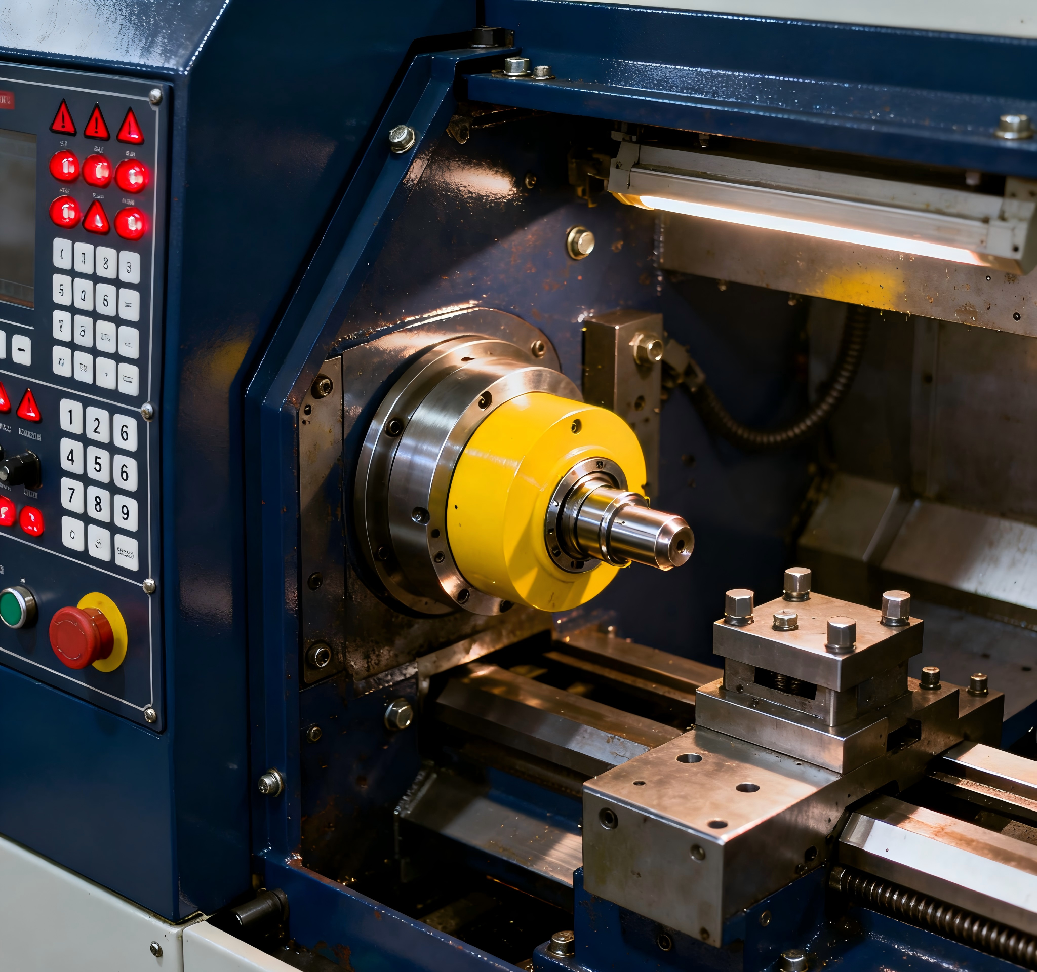
With the continuous advancement of innovation in manufacturing and breakthroughs in CNC machining technology, the components faced by the machining industry are becoming increasingly complex. This trend places higher demands on machining capabilities. In the context of increasingly intense market competition, effectively controlling machining costs while ensuring the mechanical performance and functionality of the parts has become a core issue of common concern for enterprises.
Cost optimization needs to be driven from multiple dimensions: on one hand, precise optimization can be implemented in the part design and material selection stages, such as simplifying structures and matching material properties to reduce basic machining costs; on the other hand, process upgrades are an important breakthrough. For example, replacing CNC engraving with laser engraving for text can not only meet the product’s performance requirements but also reduce auxiliary time for clamping and debugging, thereby achieving a reduction in overall costs. The following specific strategies will help design components with a more cost-effective advantage.
Avoiding Features That Cannot Be Machined by CNC
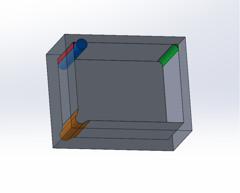
For example, when manufacturing a storage box for collectible cards using stainless steel, with a structure as shown in the diagram above, we first learn that the collectible cards are quite thin, with a thickness of about 0.3mm. We choose a φ2mm end mill (blue) for machining, but when the tool reaches the corner of the groove, we notice that some material has not been removed (red). To achieve a perfectly vertical corner, we could use Electrical Discharge Machining (EDM) or assemble the parts using multiple flat plates and screws. However, both processes can be time-consuming and costly.
Typically, we would use the smallest diameter end mill to clear the corner. For stainless steel 304, using a 0.8mm end mill, we still leave about a 0.4mm fillet (rounded corner) that is not removed. Additionally, the machining depth of the tool is limited; the length of the end mill is at most five times the diameter of the tool. Using such a small end mill is extremely time-consuming and adds unnecessary costs.
If the sharp corners of the groove are not strictly necessary, it is usually advisable to either leave the area empty (orange) or redesign the corners as rounded (green). These two design changes not only improve production efficiency but also reduce machining costs.
Reasonable use of tolerances
In the process of part design and machining, using reasonable tolerances not only ensures product quality and improves efficiency, but also effectively controls costs. Tolerance refers to the permissible range of variation between the actual size or shape of a part and the design specifications. Tolerances should be set according to the specific usage requirements of the part. Too stringent tolerances not only increase machining difficulty but may also lead to longer production cycles, thereby increasing costs.
For high-precision parts (such as mechanical drive shafts), smaller tolerances should be selected to ensure proper fit and performance. For parts that do not affect the functionality (such as housings), tolerances can be relaxed appropriately to reduce machining costs.
Reasonably using tolerances is not only the foundation for improving the precision of parts but also a method to control costs and enhance production efficiency. In the machining of parts at Horizon, before production, our engineers will reconfirm with you the necessity of strict tolerances or the dimensions that you are particularly concerned about.
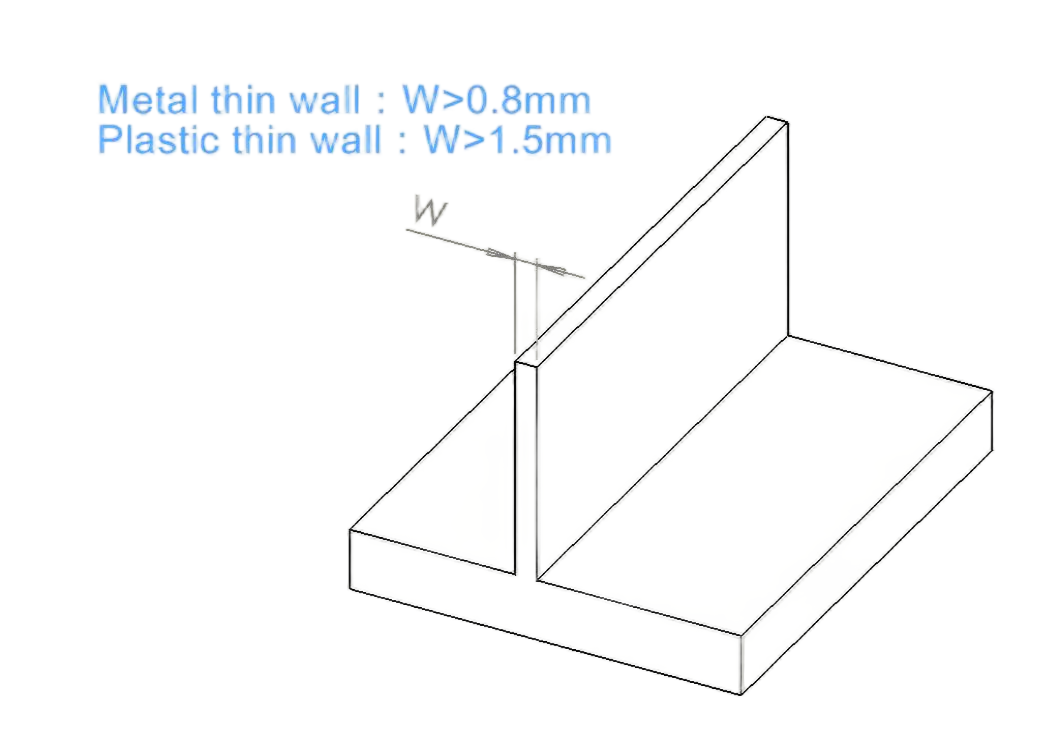
Thin-walled parts require more processing time because they are fragile. Due to their tendency to vibrate or deform, it becomes challenging to maintain accurate tolerances, and in severe cases, they may even fracture. Slow machining, the need for specialized processing techniques, and a higher scrap rate make thin-walled parts more expensive to manufacture.
On the other hand, thick-walled parts offer greater stability during machining and are more cost-effective. To keep processing costs low, it is recommended to avoid thin-wall designs. The wall thickness of metal parts should be greater than 0.8mm, while for plastic parts, it should be greater than 1.5mm.
Reduce the use of curved surface features
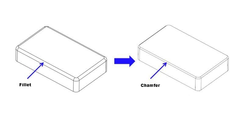
When designing components, the principle of simplicity should be followed. Complex curved surfaces should be avoided whenever possible. Achieving better surface finish on curved surfaces often requires the use of small-diameter tools, which in turn requires more processing time and increases unnecessary costs.
To optimize costs and processing time to the greatest extent, it is recommended to reduce or eliminate the use of complex curves. For example, when processing the edges of a housing, chamfering should be used instead of a rounded corner, unless the rounded corner is absolutely necessary.
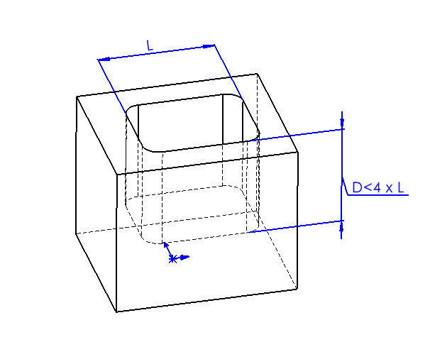
Limit the depth of deep cavities
Machining deep cavities can significantly impact the cost of CNC parts due to the large amount of material that needs to be removed, which is time-consuming. A deep cavity can cause tool overhang, tool deflection, difficulty in chip removal, and even tool breakage.
When the milling depth exceeds twice the diameter of the tool, the feed rate must be reduced, which increases machining time and part costs. For every additional doubling of the milling depth, the feed rate is halved, and the machining time increases by over 100%. Generally, the milling depth should not exceed four times the tool diameter. For example, a cavity that is 15mm wide should not be deeper than 60mm.
If deep cavities cannot be avoided, a solution is to gradually lower the end mill, removing material layer by layer. However, this process is also time-consuming. Additionally, when machining deep cavities, the tool must be tilted to the correct cutting depth, and a smooth entry requires sufficient space for the tool to operate effectively.
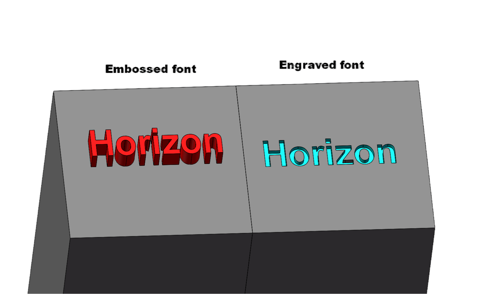
Cost Optimization of Part Marking Design
To ensure traceability for each part, text is often added to the surface during the design phase. However, designing text as embossed or engraved fonts can complicate CNC machining, as it requires using small engraving tools or the smallest diameter end mills. This increases machining time and consequently raises costs.If including text is a necessary design requirement, one alternative to reduce costs is to use laser engraving. Laser engraving eliminates the need for physical contact with tools, minimizing tool wear and adjustment needs, while allowing for precise and detailed text or logos, thereby reducing machining time and costs.
For parts with surface logos or text, silk-screen printing can be a more cost-effective solution. This method is ideal for large quantities of parts and offers an efficient way to apply text or logos without the need for intricate CNC machining.When it comes to font selection, we typically use Arial font, as it is clean, legible, and well-suited for both laser engraving and silk-screen printing.
Choosing the Right Materials
Choosing the appropriate materials during the part design phase is crucial and should be determined based on the actual performance requirements of the component. For example, when choosing between stainless steel 304 and stainless steel 316, for parts that need to be corrosion-resistant but do not require high-temperature performance, stainless steel 304 is generally recommended due to its good corrosion resistance and lower cost. On the other hand, for parts that need to withstand exposure to acids, alkalis, and high-temperature environments, stainless steel 316 should be selected, as it offers superior corrosion resistance and high-temperature stability.
Proper material selection not only enhances the performance of the components but also reduces maintenance costs over the long term, thereby controlling overall costs. By making scientifically-based material choices during the design phase, companies can optimize their cost structure and improve the competitiveness of their products in the market.
If you’re unsure which material to choose, feel free to browse our complete materials list to help you make an informed decision. For more precise recommendations, you can also upload your CAD model to our website, and our customer service team will get in touch with you promptly. Meanwhile, our engineers will assess each part of the model to determine which fall within our machining capabilities and which may pose potential risks. Our quote will clearly outline the evaluation results, allowing you to adjust your part design based on the feedback and obtain a revised quote, ensuring that the final solution meets your needs.