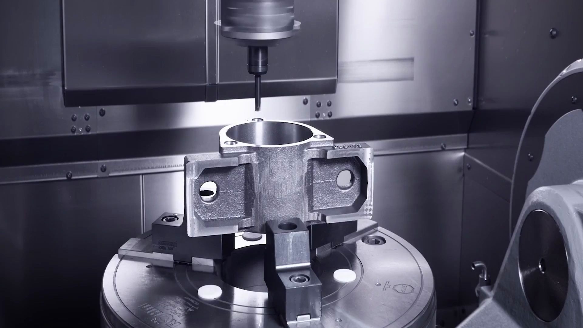
What is 5-Axis Machining?
The Development and History of 5-Axis Machining
The Development and History of 5-Axis Machining
What are the functions of each axis in a 5-Axis machine ?
-
A-axis: A rotary axis around the X-axis, used for machining inclined planes or complex surfaces.
-
B-axis: A rotary axis around the Y-axis, allowing the tool to approach surfaces that are otherwise difficult to access, thereby improving machining flexibility.
-
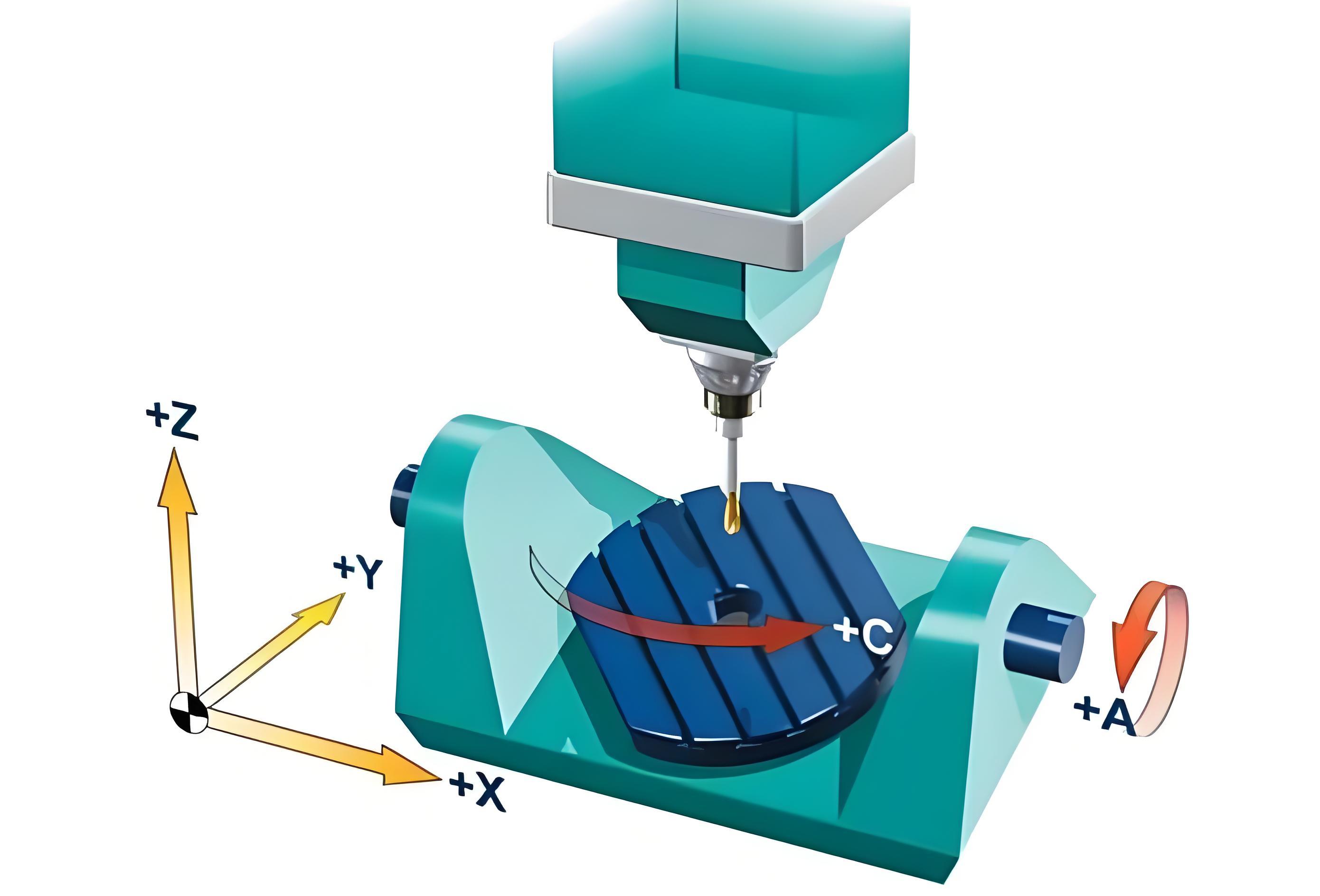
X-axis: Moves horizontally left and right, controlling the horizontal positioning of the tool or workpiece.
-
Y-axis: Moves horizontally forward and backward, working with the X-axis to achieve two-dimensional positioning within a plane.
-
Z-axis: Moves vertically up and down, enabling depth cutting of the workpiece.
-
A-axis: Rotates around the X-axis, enabling the machining of inclined or complex surfaces.
-
B-axis: Rotates around the Y-axis, allowing the tool to avoid obstacles or reach complex areas, thereby enhancing machining freedom.
What are the types of 5-Axis CNC machining?
-
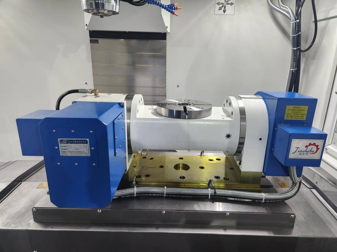
Trunnion Type
The rotary axes (usually A, B, or C) are mounted on the worktable. The workpiece is tilted and rotated by the table to change its angle. In simple terms: the workpiece moves. -
Swivel Head Type
The rotary axes are mounted on the spindle head. The workpiece remains fixed on the table, while the tool achieves multi-angle machining through spindle swinging and rotation. In simple terms: the tool moves. -
Trunnion + Swivel Hybrid Type
One rotary axis is located on the worktable, and the other on the spindle. In simple terms: both the workpiece and the tool can move. -
Dual Swivel Head Type
Both rotary axes are realized at the spindle end, while the workpiece remains completely fixed. In simple terms: the tool has dual rotations. -
Universal Machining Center
A multifunctional setup that combines five-axis milling, turning, and other operations within a single machine.
-
Trunnion type offers stronger load capacity and is suited for large or heavy workpieces.
-
Swivel head type is advantageous for machining complex curved surfaces.
-
Hybrid and dual swivel head designs balance flexibility and precision.
-
Universal machining centers represent the trend of high-end equipment toward integration and multifunctionality.
What is 3+2 Machining / 4+1 Machining?
3+2 Machining
Refers to the simultaneous movement of three linear axes (X, Y, Z), while the two rotary axes (A, B, or C) are used only for positioning. They are set to a fixed angle before three-axis machining begins, so true five-axis simultaneous motion is not achieved.
3+2 Machining, also known as Positional 5-Axis, is suitable for multi-surface workpieces, reducing the number of setups. It offers higher accuracy and flexibility than three-axis machining, but lower than true five-axis simultaneous machining.
4+1 Machining
Involves four axes (X, Y, Z + one rotary axis) moving simultaneously during machining, while the other rotary axis is used solely for positioning and does not participate in real-time interpolation. Compared to 3+2, 4+1 machining is more flexible and can perform continuous cutting on local complex surfaces, but it still cannot achieve full freeform five-axis simultaneous machining.
3+2 Machining VS 5-Axis Machining
In 5-axis machining, the choice between 3+2 positioning and 5-axis simultaneous machining mainly depends on the complexity of the workpiece and the required machining accuracy:
| 3+2 Machining | Suitable for simple workpieces with primarily planes, holes, and slots, where dimensional accuracy requirements are not high. This method simplifies programming and improves machining efficiency, making it ideal for conventional parts. |
| 5-Axis Machining | Suitable for complex workpieces with curved surfaces or high-precision requirements (e.g., impellers). It ensures the tool maintains the optimal cutting orientation relative to the workpiece, guaranteeing dimensional accuracy and surface quality. |
What are the advantages of 5-axis machining?
-
Capability to Machine Complex Parts: Five-axis machining can complete complex components in a single setup, which would otherwise require multiple machines or setups using traditional methods.
-
Reduced Setups: Multiple surfaces of a workpiece can be machined simultaneously along five axes, reducing 60% setup time and ensuring consistent accuracy.
-
High Precision: Single-setup machining avoids errors caused by repositioning, ensuring high dimensional accuracy.
-
Efficient Production: The combination of high-speed operation and precision enhances overall production efficiency.
-
Improved Surface Quality: Rotatable tools and the use of shorter cutting tools reduce vibrations and improve surface finish.
-
Lower Labor Costs: Simplified operations and fewer setups reduce labor requirements and increase automation efficiency.
What are the disadvantages of five-axis machining?
-
High Equipment Cost
Five-axis machine tools have complex structures and advanced control systems, making them significantly more expensive than three- or four-axis machines. Initial investment is relatively high.
-
Complex Programming and Operation
Five-axis machining requires specialized CAM software and intricate toolpath planning, demanding high skill levels from operators and programmers.
-
High Tooling Costs
To ensure precision and rigidity, five-axis machining often uses short or specialized cutting tools, increasing tooling expenses.
-
Difficult Maintenance and Repair
Due to the complex structure and transmission systems, maintenance and repair require professional technicians, resulting in higher costs.
In which fields is 5-Axis CNC machining applied?
-
Aerospace: Used for complex, high-precision components such as aircraft fuselage structures, blades, and engine parts.
-
Automotive: Applied in manufacturing transmissions, engine components, drive shafts, body structures, and customized parts for maintenance workshops.
-
Medical Devices: Used for artificial joints, orthopedic implants, dental restorations, and other high-precision medical products.
-
Energy and Power: Applied in the machining of turbine blades, pump housings, and wind turbine blades.
-
Semiconductor and Electronics: Used for high-precision mechanical parts, molds, and substrates.
-
Military: Applied in machining small weapon components and large parts for submarines and aircraft.
Five-Axis Machining Performance Improvement Guide
1. Understanding the Equipment
Due to the high investment cost of five-axis machines, it is essential to fully understand the equipment capabilities and your machining requirements before purchase:
Evaluate whether five-axis machining is necessary, for example, when dealing with complex surfaces or spatial interference components.
Choose the appropriate machine model and configuration based on the type of machining to avoid over-investment or underutilization.
Clearly defining your needs helps save unnecessary costs and maximizes equipment utilization.
2. Simulation Verification
Five-axis machining involves complex tool paths, and programming errors or collisions can easily cause part scrap:
Before transferring the program to the machine, use CAD/CAM software to perform machining path simulation and verification.
Focus on checking collisions, tool length compensation, and leftover material.
Identifying potential issues in advance can reduce machine damage and material waste while improving machining safety.
3. Tool Optimization
The selection and use of tools directly affect machining accuracy and efficiency:
Use tools specifically designed for five-axis machining and ensure compatibility with your machine and fixtures.
Tools should be easy to install and remove, minimizing manual intervention, and must be compatible with fixture design.
Proper tool path planning and cutting parameters can extend tool life and maintain surface quality.
4. Programming Enhancement
Program optimization can reduce unnecessary tool passes, improve surface finish, and reduce machine load.
Reasonable path planning not only extends tool life but also improves overall machining stability.
It is recommended to hire experienced programming professionals to ensure the program is efficient, safe, and accurate.
Frequently Asked Questions
1.How to determine whether a part requires 5-axis or 3-axis machining?
| Criteria | 3-Axis Machining | 5-Axis Machining |
|---|---|---|
| Geometry | Flat surfaces, straight holes, standard slots | Complex curved surfaces, inclined holes, variable-angle slots, multi-surface continuous machining |
| Efficiency | Achievable with multiple setups, efficiency not critical | Multi-surface machining in one setup, high efficiency required |
| Tool Access | Tool can easily reach machining areas, no significant interference | Presence of deep cavities, inclined surfaces, or restricted spaces where 3-axis tools cannot reach |
| Typical Parts | Plates, mold bases, simple cavities, straight holes, keyways | Impellers/blades, turbines, aerospace components, medical implants, complex mold cavities |
2.Why is 5-Axis machining programming difficult?
The difficulty of five-axis machining programming is greater than that of three-axis machining, mainly because five-axis machining not only requires controlling the tool position in three-dimensional space but also needs to continuously adjust the tool axis angle and orientation. Unlike three-axis machining, five-axis programming requires the programmer to plan the tool’s entry angle, tilt direction, and machining path based on the geometry of the workpiece. Even small adjustments in the tool axis can significantly impact the surface quality of the machined part.
As a result, five-axis machining programming is more complex and demands higher technical expertise than three-axis machining. Programmers must possess precise spatial planning abilities and a deep understanding of the dynamic control of the tool to ensure machining efficiency and accuracy.
3.What common interference issues occur in five-axis machining?
4.How to avoid overcutting or undercutting during the five-axis machining process?
Latest Post

Liquid Silicone Rubber Molding: Process, Benefits, Applications, and Design Considerations

What is a 5-axis machine? The differences from 3-axis machines and their applications.

What Is a Tack Weld? Definition, Purpose, and Applications

How to Remove Burrs from CNC Machined Parts: Common Deburring Methods Explained