Our CNC machines can efficiently complete the milling or turning of parts within 24 hours. Although advanced technology enables this high production capacity, human factors remain the key to success or failure. Based on practical experience, design-related oversights are often the core cause of issues during part processing. Avoiding the following common design errors can not only optimize the part design, shorten the processing cycle, but also potentially reduce the final manufacturing cost.

Avoid High and Thin Wall Features

It is relatively simple to design high and thin wall features in CAD software, but it becomes quite challenging during CNC machining. CNC tools are typically made from high-hardness materials. Although the material of the tools is hard, they still experience slight bending under cutting forces, which in turn affects the material being cut (the bending direction is opposite to that of the tool’s bending).

When the wall features are high and thick, the resulting machined part often exhibits a thicker bottom wall than the top, and the surface may show wave-like patterns. This is caused by uneven cutting due to tool deflection. This phenomenon not only affects the quality of the part but also significantly impacts the product’s appearance and dimensional accuracy.

For high and thin wall features, the situation is even more severe. After machining, thin walls may bend or even break, especially if improper machining processes are used. Thin-walled parts require lower cutting speeds, precise process control, and have higher scrap rates, all of which increase manufacturing costs. As a result, the production cost of thin-walled parts is generally higher.

In contrast, thick-walled parts have greater stability during machining, which effectively reduces the risk of deformation. The machining process is also less prone to errors, leading to lower production costs and scrap rates. To keep processing costs low and improve machining quality, it is recommended to avoid excessively thin wall features in the design. Typically, metal parts should have a wall thickness greater than 0.8mm, while plastic parts should have a wall thickness greater than 1.5mm to ensure stability and accuracy during machining.

Embossed Font Design on Metal or Plastic Surface

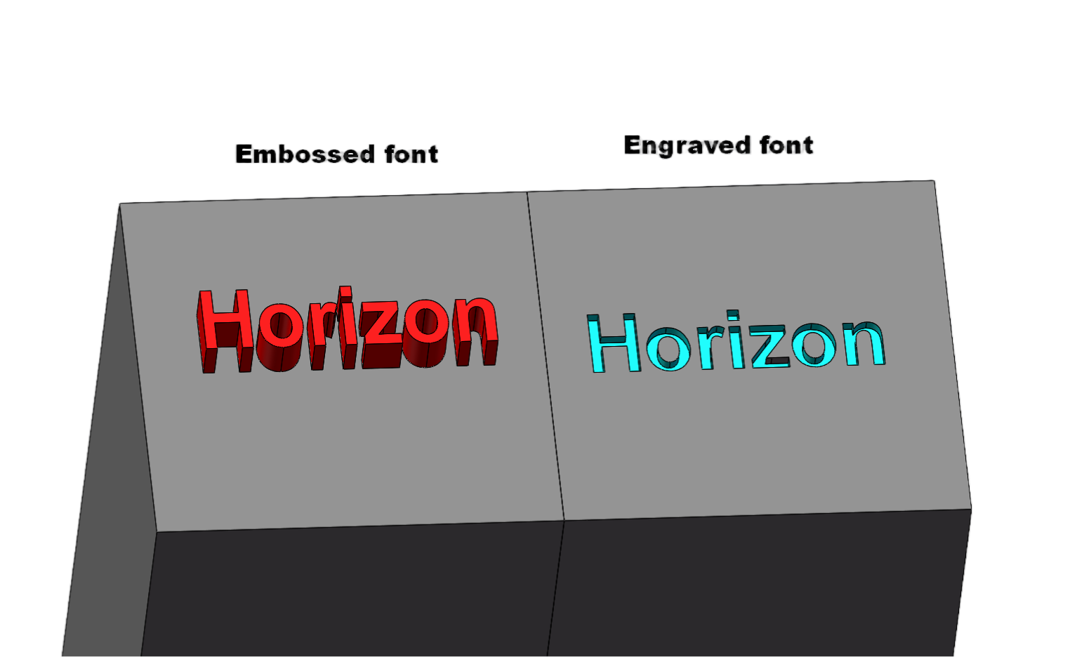
Avoid Small or Raised Text

To ensure each part is traceable or to mark the company logo, text is often added to the surface of parts during the design phase. However, adding text increases costs. Machining text usually requires very small engraving tools or end mills with a minimal diameter, which results in slower machining speeds and increases processing time. The smaller the text, the higher the cost. Larger text, on the other hand, reduces costs. Whether the text is raised or recessed, material must be milled away.

If text is a necessary design feature, it is recommended to use recessed text. Laser engraving is an alternative solution to reduce costs. For font selection, we typically use Arial because of its simplicity and readability.

Avoid Potentially Unnecessary Small Grooves

During the part production process, we often encounter groove designs (such as internal right angles or small grooves) that are intended to reduce the part’s weight or provide assembly space for other components. However, for larger-sized tools, internal 90° right angles and small grooves may appear relatively large in size. Machining these features typically requires using multiple tool sizes, and the smaller the tool, the slower the machining speed, which leads to more time required and, consequently, increased costs.

To avoid this, it’s essential to first confirm whether these small groove features are truly necessary. If they are only intended to reduce the part’s weight, it may be worth reconsidering the design to avoid unnecessary material removal costs. By increasing the corner radius, we can use larger cutting tools, which shortens machining time and reduces costs.

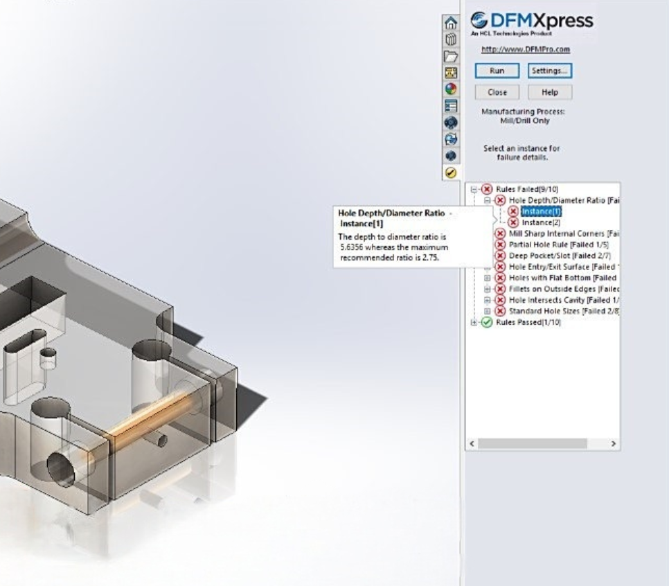
Limit the depth of deep cavities

Deep Cavity Schematic Diagram for Injection Molding or Casting
Machining deep cavities can significantly impact the cost of CNC parts due to the large amount of material that needs to be removed, which is time-consuming. A deep cavity can cause tool overhang, tool deflection, difficulty in chip removal, and even tool breakage.

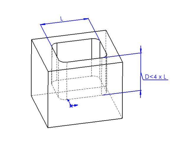
When the milling depth exceeds twice the diameter of the tool, the feed rate must be reduced, which increases machining time and part costs. For every additional doubling of the milling depth, the feed rate is halved, and the machining time increases by over 100%. Generally, the milling depth should not exceed four times the tool diameter. For example, a cavity that is 15mm wide should not be deeper than 60mm.

If deep cavities cannot be avoided, a solution is to gradually lower the end mill, removing material layer by layer. However, this process is also time-consuming. Additionally, when machining deep cavities, the tool must be tilted to the correct cutting depth, and a smooth entry requires sufficient space for the tool to operate effectively.

Radii design

CNC tools are typically cylindrical, and even the smallest diameter tools are only 0.8mm. Therefore, for sharp internal corners in grooves, the tool cannot fully remove the material. To remove the remaining material, EDM (Electrical Discharge Machining) is required, which is both time-consuming and costly.

In CNC machining, the internal corners of grooves are usually rounded, and the radius of the corner is determined by the diameter of the tool. When designing parts, replacing sharp internal corners with rounded corners greatly simplifies the machining process. The larger the radius of the corner, the larger the diameter of the tool that can be used, which allows for faster milling and, consequently, lower costs.

Hole Design

In hole design, engineers should aim to select hole diameters that match standard drill sizes. While non-standard diameters can also be machined, they require the use of end mills, which increases machining difficulty and cost. In addition to the hole diameter, the depth must also be carefully considered. Typically, hole depth should not exceed approximately 10 times the diameter, although deeper holes can be achieved with special drills.

When drilling holes with a standard drill, the hole bottom will naturally be conical. For blind holes (holes that do not pass completely through the workpiece), the bottom will also be conical. If a flat-bottomed hole is required, an end mill must be used to ensure the bottom surface is flat.

CNC part with drilled thread (tapped hole) following manufacturability guidelines for precision machining

Thread Design

In thread design, engineers should prioritize the use of standard thread specifications. Although non-standard thread diameters can be manufactured, they often require special tools or processes. Moreover, to ensure proper thread assembly, custom inspection tools may also be necessary. This not only increases machining complexity but also significantly raises manufacturing costs. Therefore, it is recommended to adopt standardized thread specifications during the design stage to improve machining efficiency and effectively reduce overall costs.

When machining parts with threaded features, it is also necessary to provide 2D drawings. This is because thread information in 3D models is often incomplete—typically represented only as simplified geometry or annotations—making it difficult to accurately convey critical parameters such as thread specification, depth, and type. By clearly defining these details in 2D drawings, machining errors can be effectively avoided, ensuring assembly accuracy and machining quality of threaded parts.

Proper Use of Tolerances

In part design and machining, applying proper tolerances not only ensures product quality and improves efficiency but also helps effectively control costs. Tolerance refers to the allowable deviation of a part’s actual dimension or shape from the design specification. Tolerances should be defined based on the specific functional requirements of the part. Overly strict tolerances not only increase machining difficulty but may also extend production cycles, thereby driving up costs.

CAD Software for CNC Milling Design

Most CAD software can be used to design CNC milled parts. The following two design software packages are the most widely used in the industry:

SOLIDWORKS

Developed by Dassault Systèmes, SOLIDWORKS is a comprehensive CAD software that integrates tools for verifying CNC milling designs. Its built-in DFMXpress (Design for Manufacturability tool) allows users to set milling constraints according to manufacturer requirements (such as the maximum ratio of hole depth to diameter). This tool can also detect unmachinable features (such as areas that the tool cannot reach) and automatically highlight areas that need the user’s attention, reducing potential risks during the design phase.
DFMxPRESS manufacturability analysis tool checking design for manufacturability in injection molding, machining, sheet metal and more

Fusion 360

Developed by Autodesk, Fusion 360 is highly favored by engineers and machinists due to its optimization for CNC machining. Like other specialized CAD software, it supports both general and custom constraints to ensure that no unmachinable features appear in the design. Additionally, Fusion 360 integrates CAM functionality, allowing it to directly generate toolpaths for CNC milling machines. If the design contains unmachinable features, the software will be unable to generate corresponding toolpaths, thus alerting users to problems at the design stage.

Horizon CNC Milling Services

Horizon has years of experience in CNC milling and can efficiently transform your designs into high-quality parts. You don’t need to worry about minor design issues: simply upload your CAD files, and we will provide a manufacturability analysis report to help optimize your design and ensure smooth production.

Latest Post

  • Liquid silicone rubber molding machine in operation producing precision parts showing process and benefits of LSR molding

    Liquid Silicone Rubber Molding: Process, Benefits, Applications, and Design Considerations

  • Diagram comparing 3-axis linear movement with 5-axis CNC including A and C rotational axes.

    What is a 5-axis machine? The differences from 3-axis machines and their applications.

  • Tack welding process used to temporarily fix sheet metal components before final welding in industrial fabrication

    What Is a Tack Weld? Definition, Purpose, and Applications

  • Illustration showing common deburring methods for CNC machined parts, including manual deburring, mechanical deburring, dry ice deburring, chemical deburring, and electrochemical deburring, with burr removal process steps.

    How to Remove Burrs from CNC Machined Parts: Common Deburring Methods Explained